#1 rule of troubleshooting: You shall measure voltages!
Sounds like you might have lost a supply rail or something. Also, a loud pop indicates that there may be substantial DC offset on the output - not good for the cans!
An extensive troubleshooting section has been provided for the O2:
NwAvGuy: O2 Details
I suggest going through the step-by-step DC voltage list backwards, since you are starting from the completed product.
Hello everyone,
I am investigating an issue with JDS Labs OBJECTIVE2+ODAC combo rev-b model. Here is what happens:
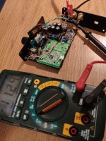
I did go over the steps Mooly described (thank you!) and all passed. The one interesting thing I noticed though is the DC voltage on outputs - see attached photo. Is this normal? What else I should look at any ideas?
I am investigating an issue with JDS Labs OBJECTIVE2+ODAC combo rev-b model. Here is what happens:
- When I plug in to headphone out, start the O2 and play musing nothing is audiable
- When I try to move the headphone jack back and forth the music comes up but with very loud pops and crackles, seems like my test headphones are about to blow up
I did go over the steps Mooly described (thank you!) and all passed. The one interesting thing I noticed though is the DC voltage on outputs - see attached photo. Is this normal? What else I should look at any ideas?
Attachments
I've only ever looked into faultfinding on the O2 headphone amp, not the DAC.
First thing to say is that whether a fault exists or not, physical movement should not cause the symptoms to alter, something you say yours is doing. That needs looking into first. Perhaps the DC offset resolves at the moments you hear the music.
Alternatively you can trouble shoot the DC offset present by beginning with voltage measurements on the parallel opamp output stages. The output stage is AC coupled at its input and so you should only measure supply voltage on pins 4 and 8 of the chips. All other pins should be at zero volts DC.
Alternatively you can trouble shoot the DC offset present by beginning with voltage measurements on the parallel opamp output stages. The output stage is AC coupled at its input and so you should only measure supply voltage on pins 4 and 8 of the chips. All other pins should be at zero volts DC.
So I measure parallel opamp 4556 DC voltage on pins 4 and 8 to common ground located at C2-5 and get correct voltage (~11.7V). Then I checked the voltage same way on other pins and also get +/- ~10-12V. Do I have to measure differently or something is wrong?
That doesn't sound right. You should have +11 V and -11 V on pins 8 and 4 (respectively), and all the other pins should be at ~0 V. Maybe compare to NJM2068, which has the same pinout.
Somehow I suspect one of your supply voltages is missing or at least not making it through. Check at the regulators, series diodes, NJM2068 4/8 and NJM4556A 4/8. It has got to get lost somewhere. Check continuity between known good and bad spots.
Somehow I suspect one of your supply voltages is missing or at least not making it through. Check at the regulators, series diodes, NJM2068 4/8 and NJM4556A 4/8. It has got to get lost somewhere. Check continuity between known good and bad spots.
So I measure parallel opamp 4556 DC voltage on pins 4 and 8 to common ground located at C2-5 and get correct voltage (~11.7V). Then I checked the voltage same way on other pins and also get +/- ~10-12V. Do I have to measure differently or something is wrong?
As sgrossklass says... it does sound like a missing rail.
Use the common ground point at the junction of C2/3/4 and 5 and connect your meter black lead here.
You should have PLUS 11 volts or so on pin 8 and MINUS 11 on pin 4. All other pins should be zero.
That doesn't sound right. You should have +11 V and -11 V on pins 8 and 4 (respectively), and all the other pins should be at ~0 V. Maybe compare to NJM2068, which has the same pinout.
Somehow I suspect one of your supply voltages is missing or at least not making it through. Check at the regulators, series diodes, NJM2068 4/8 and NJM4556A 4/8. It has got to get lost somewhere. Check continuity between known good and bad spots.
I did same test on NJM2068 4/8 reads fine at ~11V, other pins are 0V. NJM4556A as mentioned before - most of the pins show +/- 11.7V.
I also did go through the raw DC voltages test mentioned in nwavguy guide here
All voltages are as described except the P2 where I measure ~11V

You mention continuity tests - what exactly should I check?
Thanks for your help guys !
You have to be clear on the exact readings you get Copy and paste the last part of this post with actual readings, it will only take a couple of minutes and be sure to include the correct polarity.
A single pin can not be at -/+11, it has to be at some distinct - or + voltage, it can't be both.
Similarly:
means 11 volts AC to me
The devil is in the detail, we're not being picky, it is just so fundamental to interpreting what is going on.
U3 4556
Pin1=
Pin2=
Pin3=
Pin4=
Pin5=
Pin6=
Pin7=
Pin8=
U4 4556
Pin1=
Pin2=
Pin3=
Pin4=
Pin5=
Pin6=
Pin7=
Pin8=
Copy and paste the last part of this post with actual readings, it will only take a couple of minutes and be sure to include the correct polarity.A single pin can not be at -/+11, it has to be at some distinct - or + voltage, it can't be both.
Similarly:
All voltages are as described except the P2 where I measure ~11V
means 11 volts AC to me
The devil is in the detail, we're not being picky, it is just so fundamental to interpreting what is going on.
U3 4556
Pin1=
Pin2=
Pin3=
Pin4=
Pin5=
Pin6=
Pin7=
Pin8=
U4 4556
Pin1=
Pin2=
Pin3=
Pin4=
Pin5=
Pin6=
Pin7=
Pin8=
You have to be clear on the exact readings you get
A single pin can not be at -/+11, it has to be at some distinct - or + voltage, it can't be both.
Similarly:
means 11 volts AC to me
The devil is in the detail, we're not being picky, it is just so fundamental to interpreting what is going on.
Sure thing, I can measure what you need to get things sorted out. Below all measurements of DC voltage:
U3 4556
Pin1=-11.22
Pin2=-11.22
Pin3=-10.55
Pin4=-11.74
Pin5=-10.55
Pin6=-11.22
Pin7=-11.22
Pin8=11.71
U4 4556
Pin1=-11.47
Pin2=-11.47
Pin3=-10.87
Pin4=-11.74
Pin5=-10.87
Pin6=-11.47
Pin7=-11.47
Pin8=11.71
The stand out error has to be pin 5 and 3. That should be ground referenced via R12/13.
Check the voltage on each side of those resistors. One side must be grounded as shown on the circuit diagram. If you have this negative 10 to 11 volts on both sides then there has to be a break in the ground print to that area of the board.
If the above checks out OK then remove the two IC's from their sockets and recheck ALL the pin voltages again. Apart from pins 4 and 8, all have got to be zero.
Hi everybody! We don't know the background on transcendent's exemplar of the O2, but I find it strange that JDS could be selling O2s with this kind of fault?..
I'm sure this is an exception, but I've already read from reviewers checking the inside of JDS assembled O2s that the soldering job isn't always first class...
I'm sure this is an exception, but I've already read from reviewers checking the inside of JDS assembled O2s that the soldering job isn't always first class...
One side 0, other ~ -11 volts for both resistors.The stand out error has to be pin 5 and 3. That should be ground referenced via R12/13.
Check the voltage on each side of those resistors. One side must be grounded as shown on the circuit diagram. If you have this negative 10 to 11 volts on both sides then there has to be a break in the ground print to that area of the board.
All pins except 4 and 8 are 0 volts after I removed the IC's.If the above checks out OK then remove the two IC's from their sockets and recheck ALL the pin voltages again. Apart from pins 4 and 8, all have got to be zero.
Any other checks I can make?
Hi CHiroshi,Hi everybody! We don't know the background on transcendent's exemplar of the O2, but I find it strange that JDS could be selling O2s with this kind of fault?..
I'm sure this is an exception, but I've already read from reviewers checking the inside of JDS assembled O2s that the soldering job isn't always first class...
It was working fine for several years so more likely some component broke. The soldering should be fine I guess.
Hi CHiroshi,
It was working fine for several years so more likely some component broke. The soldering should be fine I guess.
Ok, good to hear!
I'm sure you'll get it fixed, with the help of Mooly and all the other wizards in this forum!

Ok, good to hear!
I'm sure you'll get it fixed, with the help of Mooly and all the other wizards in this forum!
Thanks CHiroshi
One side 0, other ~ -11 volts for both resistors.
All pins except 4 and 8 are 0 volts after I removed the IC's.
Any other checks I can make?
Very odd as that points to faulty chips... which is almost unheard of tbh.
You could remove the 2068 and fit it in place of either one of the 4556's and see if the voltages are now correct in that location. Leave the 2068 spot vacant.
Its odd because at the beginning you mentioned be able to move headphone connectors and hear music.
Lets work with what you have though... these incorrect voltages.
You could remove the 2068 and fit it in place of either one of the 4556's and see if the voltages are now correct in that location. Leave the 2068 spot vacant.
I get +11 volts at pin 8, -11 volts at pin 4. All other pins are at 0V.
Its odd because at the beginning you mentioned be able to move headphone connectors and here music.
I could hardly call it music, more like very loud noise/popping and silently in the background some music coming through.
Are 4556's hard to get for replacement?
- Home
- Amplifiers
- Headphone Systems
- The Objective2 (O2) Headphone Amp DIY Project