Yeah, the answer is agdr's booster board!
O2 headamp output booster PCB
Maybe it was the answer a few months ago, but you can't get them anymore. I'd even pay the $66 to get 4pcb.com to print up a single PCB, if we had access to the gerber or drill files or whatever's needed :/
I've got two, and I'm thinking of reverting one of my O2s to original. I could sell you the booster board. PM me if that sounds interesting and I'll tell you more!Maybe it was the answer a few months ago, but you can't get them anymore. I'd even pay the $66 to get 4pcb.com to print up a single PCB, if we had access to the gerber or drill files or whatever's needed :/
")
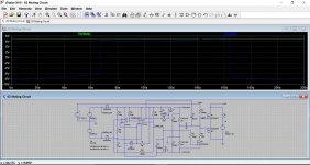
Mting circuit idea for the 02
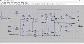
This is just an idea which seems OK as a simulation and so should translate to a real circuit.
The muting circuit is the bit at the right of the diagram. All the rest is standard 02 powersupply from an earlier simulation showing how the low voltage cut-off worked.
The mute consists of a FET solid state relay which is the two FET's. The lower the on resistance the better (Rds). This relay shorts the audio output.
The FET's are permanently biased on via a 10meg from the positive battery supply. This means the mute is permanently active.
The FET's are turned off (unmuted) when FET 'M3' is turned on via R7 when the appropriate comparator output goes high.
The FET relay is turned off quickly via shottky diode D2.
Possible issues...
1/ The O2 opamp output stage may not be able to find its operating point with a 'short' across the output. If this were a problem then the 1 ohm series output resistors could be increased slightly. It may be fine though.
2/ The FET types seem fairly critical. Many of the modern high performance low Vgs threshold devices provided in the LTSpice models are fine, the older common devices such as 2N7002 are not.
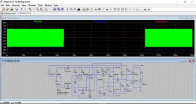
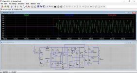
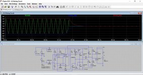
This shows the on/off behaviour. The voltage source at the right represents a continuous audio source that can be shorted to mute it.
This is just an idea which seems OK as a simulation and so should translate to a real circuit.
The muting circuit is the bit at the right of the diagram. All the rest is standard 02 powersupply from an earlier simulation showing how the low voltage cut-off worked.
The mute consists of a FET solid state relay which is the two FET's. The lower the on resistance the better (Rds). This relay shorts the audio output.
The FET's are permanently biased on via a 10meg from the positive battery supply. This means the mute is permanently active.
The FET's are turned off (unmuted) when FET 'M3' is turned on via R7 when the appropriate comparator output goes high.
The FET relay is turned off quickly via shottky diode D2.
Possible issues...
1/ The O2 opamp output stage may not be able to find its operating point with a 'short' across the output. If this were a problem then the 1 ohm series output resistors could be increased slightly. It may be fine though.
2/ The FET types seem fairly critical. Many of the modern high performance low Vgs threshold devices provided in the LTSpice models are fine, the older common devices such as 2N7002 are not.
This shows the on/off behaviour. The voltage source at the right represents a continuous audio source that can be shorted to mute it.
Attachments
Stupid question maybe, but what about when AC powered (and no batteries)?
A good question. The idea is to always have the battery supply in place. For a design that catered for 'no battery' then a separate 'supercap' charged to 5 volts could be an option.
As I say, this is all theory and all simulation, but that said the results should be in the right ballpark.
One curious fact is that the circuit seems to perform exactly the same even without the 10meg resistor in place.
Here is the .asc file if anyone wants a play. All standard library parts (LTXVII)
Attachments
Need help! Can I use cat5,6 wires to hook 1/4 inch headphone out to pcb while i attach it to chassis?
https://images.homedepot-static.com...n/spt-voice-data-cable-cat5-1000g-64_1000.jpg
These little wires.
https://images.homedepot-static.com...n/spt-voice-data-cable-cat5-1000g-64_1000.jpg
These little wires.
Has anyone moved the volume pot to the input, and shunted by the current pot position? Is that as straightforward an operation as it seems? Is it even worth the investment in a better pot? I know it probably won't make any difference with the vast majority of headphones, but suppose I have one of the exceptions.
After moving the o2 into a beautiful carved antique wooden box, there's room for more stuff so I'm thinking about putting a precision stepped attenuator on the input, and I'll mount it on the top of the box.
The TKD 10K, 2CP-2511 Series gets great reviews and it's only $99. Or is it worth it to go whole-hog and build a Clone Note? Something even better for under $200?
I don't see why not. Cat5 makes great audio cable IME
After moving the o2 into a beautiful carved antique wooden box, there's room for more stuff so I'm thinking about putting a precision stepped attenuator on the input, and I'll mount it on the top of the box.
The TKD 10K, 2CP-2511 Series gets great reviews and it's only $99. Or is it worth it to go whole-hog and build a Clone Note? Something even better for under $200?
Need help! Can I use cat5,6 wires to hook 1/4 inch headphone out to pcb while i attach it to chassis?
https://images.homedepot-static.com...n/spt-voice-data-cable-cat5-1000g-64_1000.jpg
These little wires.
I don't see why not. Cat5 makes great audio cable IME
Moving the volume control would lose you the precisely defined input characteristic that the first opamp gives, and whichever way you cut it that is a less satisfactory way of doing things imo. It will also increase the noise contribution because the front end would not see its noise contribution reduced by lowering the volume (as it does now).
Im a noob so I must ask about internal wiring of amplifiers. If I use cat5 or cat6 cables, should I use solid copper type or other one. If I remove PVC shroud from cable and expose those 8 wires because I need only 2 or 3 to hook up audio in or audio out, do those wires lose shielding?
One more question do I always twist those little wires when I hook them inside amp?
One more question do I always twist those little wires when I hook them inside amp?
Solid or stranded wont make any difference for a short run to a headphone socket.
When you mentioned cat5 I thought you meant just pulling out some of the wire to use as general purpose hookup wire, not retaining its twisted configuration. Ideally you should not run left and right channels through a twisted pair although I suspect in practice for such a short run that it would be fine. Possible problems would be 'mutual coupling' between the twisted wires if you did do that.
The common ground connection can be another twisted pair i.e. use both conductors for ground.
Or you can use three pairs, one for left, one for right and one for ground.
If you wanted metres of the stuff then there could be issues with the capacitance of the cable upsetting the O2's opamp stages and causing instability.... but you would be into metres and metres of the stuff.
One more question do I always twist those little wires when I hook them inside amp?
A good joint should rely on mechanical integrity first and solder second. So it depends what you are connecting to. Do what seems as though it will give the best connection for each joint such that there is good contact to begin with. You should never let the solder be a 'bridge' in the connection, get the mechanical integrity right first and then apply solder to secure.

That looks OK although the white looks better than red (but its a bit blurry so hard to be sure). Heat the centre pin, push the wire into the hole and apply solder.
I think he was mostly asking about the kind of wire, rather than the soldering job.
I don't think it really matters for such short distances, and it doesn't look as if the cable you used has any shielding, unless you just cut it and left it unconnected. I'd use twisted pairs, just because I think it looks nice!..
Ideally you should not run left and right channels through a twisted pair although I suspect in practice for such a short run that it would be fine. Possible problems would be 'mutual coupling' between the twisted wires if you did do that.
Do you mean using the conductors in one twisted pair for L and R, and then using another pair for the grounds?
In my O2, I used one twisted pair for L + its ground, and another pair for R + its ground. That should be all right?
- Home
- Amplifiers
- Headphone Systems
- The Objective2 (O2) Headphone Amp DIY Project