It sounds like you are going to struggle with this ")
You just change the meter setting and switch it to an AC voltage range. That will allow you to check that the 12 volts AC from the adapter is present. The wall power supply adapter should be an AC type rather than a DC one. That is very important.
You just change the meter setting and switch it to an AC voltage range. That will allow you to check that the 12 volts AC from the adapter is present. The wall power supply adapter should be an AC type rather than a DC one. That is very important.
It seems to show there is no output from the AC adapter. A 200 volt range would resolve 12 volts as 012.
Can we be certain that your adapter is an AC output type ?
Just for interest, if you set your meter to DC volts and repeat the test, do you see any voltage ? (you should not see any)
That's no problem at all
Can we be certain that your adapter is an AC output type ?
Just for interest, if you set your meter to DC volts and repeat the test, do you see any voltage ? (you should not see any)
And I am very thankful for the patience you give to me.
That's no problem at all
The 12 volts AC should be present whenever the wall power unit is on.
If you have no AC voltage present, then as well as doing the tests above you should also disconnect the O2 from the power supply and then see if the voltage then appears from the wall unit.
In other words test the wall unit without it being connected to the O2.
We can also test the rest of the O2 with batteries if you want.
So i just measured this (o2%2520voltages%2520u2%2520only%255B14%255D.png (image) )
I got wrong values on r24 - instead of -11.4 i got -9,25. And on top o*oo u2 i got 7 instead of 9,8. What could that mean and what should i measure next? (everything else is fine)
I got wrong values on r24 - instead of -11.4 i got -9,25. And on top o*oo u2 i got 7 instead of 9,8. What could that mean and what should i measure next? (everything else is fine)
It points to the unregulated supplies being low.
You need to follow very carefully the guide I linked to before. This is the first part:
Checking the supplies...
The unit must first be put into a state that allows all critical voltages to be measured.
Preparation.
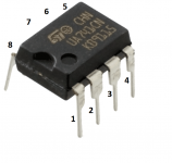
1) Remove ALL opamps and the comparator. Thats U1 through to U4
2) Make sure S1 is OFF.
3) Remove any batteries.
Measurement.
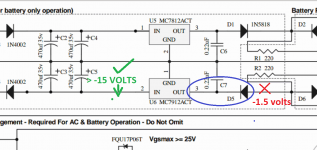
1) With your meter set to DC volts and with the BLACK meter lead firmly connected to ground (that is the common junction of C2, C3, C4 and C5 etc) measure the voltage on the striped end of D3. It should be higher than PLUS 15 volts and lower than PLUS 28 volts.
2) Keeping the BLACK lead on ground measure the DC voltage on the NON striped end of D4. It should be higher than MINUS 15 volts and lower than MINUS 28 volts.
If those conditions are OK now check the output of the two regulators. If the above readings were incorrect then you have a problem with either the AC input, a problem with the two rectifier diodes or a problem with incorrect or faulty regulators causing a short or partial short. Make sure that a 7812 is fitted for U5 and a 7912 for U6. Also make sure any electroylitics are fitted correctly with respect to polarity.
Checking the output of the regulators.
The BLACK meter lead is kept on ground unless otherwise stated.
1) Measure the DC voltage on the striped end of D1. It should be 11.5 to 12 volts approximately.
2) Measure the DC voltage on the NON striped end of D5. It should be MINUS 11.5to 12 volts DC approximately.
If you have incorrect readings for the plus and minus 12 volts yet have correct input voltages to the regulators, then the problem can only be either the regulators themselves or incorrectly fitted D1 and D5.
You need to follow very carefully the guide I linked to before. This is the first part:
Checking the supplies...
The unit must first be put into a state that allows all critical voltages to be measured.
Preparation.
1) Remove ALL opamps and the comparator. Thats U1 through to U4
2) Make sure S1 is OFF.
3) Remove any batteries.
Measurement.
1) With your meter set to DC volts and with the BLACK meter lead firmly connected to ground (that is the common junction of C2, C3, C4 and C5 etc) measure the voltage on the striped end of D3. It should be higher than PLUS 15 volts and lower than PLUS 28 volts.
2) Keeping the BLACK lead on ground measure the DC voltage on the NON striped end of D4. It should be higher than MINUS 15 volts and lower than MINUS 28 volts.
If those conditions are OK now check the output of the two regulators. If the above readings were incorrect then you have a problem with either the AC input, a problem with the two rectifier diodes or a problem with incorrect or faulty regulators causing a short or partial short. Make sure that a 7812 is fitted for U5 and a 7912 for U6. Also make sure any electroylitics are fitted correctly with respect to polarity.
Checking the output of the regulators.
The BLACK meter lead is kept on ground unless otherwise stated.
1) Measure the DC voltage on the striped end of D1. It should be 11.5 to 12 volts approximately.
2) Measure the DC voltage on the NON striped end of D5. It should be MINUS 11.5to 12 volts DC approximately.
If you have incorrect readings for the plus and minus 12 volts yet have correct input voltages to the regulators, then the problem can only be either the regulators themselves or incorrectly fitted D1 and D5.
OK, so that seems to show there is a problem within the blue ellipse. You are now going to have to very carefully check that the -15 volts is reaching the regulator input pin. Be very careful not to short the pins out when measuring. Also check the voltage directly on the output pin of the regulator.
This particular problem could be broken or 'lifted' print around a solder pad on the regulator or on the diode D5.
This particular problem could be broken or 'lifted' print around a solder pad on the regulator or on the diode D5.
Attachments
You say that all was good except for D5, and so I take it U5 is all correct and that it has the correct +12 volts present. Yes
That means you measured at least -15 volts on the point I have marked on the diagram. All you do now is check that the -15 is reaching the actual leg (pin 2) of the regulator.
If that is OK then you check the voltage on pin 3 which is the output. It will either be present or not.
That means you measured at least -15 volts on the point I have marked on the diagram. All you do now is check that the -15 is reaching the actual leg (pin 2) of the regulator.
If that is OK then you check the voltage on pin 3 which is the output. It will either be present or not.
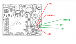
What point do you mean? I didnt understand clearly, sorry. I dont know if you got my point with explaining the values so i did this Imgur: The most awesome images on the Internet . And i am sure i shorted regulator. Should i get new one or is something else broken too?
Those voltages look basically good
You should find the voltages on U6 are negative. So -24 and -12. Yes ? (make sure they are).
If so, then you must have an open circuit connection between the regulator and the diode D5, or (unlikely) the diode is open circuit (or fitted wrong way around).
You must end up with the -12 volts on both sides of diode D5.
Attachments
The regulators are tough, and your measured voltages show they are working OK. The spark would be one of the capacitors discharging.
So your voltages up to now are all good.
We now carry on with this:
See if all that checks out OK.
So your voltages up to now are all good.
We now carry on with this:
Checking the voltage comparator and switched output rails.
1) Disconnect the AC supply and turn ON S1. Wait for 1 minute to allow the caps to discharge and then fit just U2 in its socket making sure it is the right way around.
2) Apply AC power and ensuring S1 is still ON measure the DC voltages at pins 8 and pins 4 of the remaining empty IC sockets. There should be PLUS 11.5 to 12 volts DC on pin 8 and MINUS 11.5 to 12 volts on pin 4.
If the voltages are low or missing then there is a problem around U2 and the FET rail switches. If they are correct then you should now check the comparator operation (next step below)
See if all that checks out OK.
May i ask which pins are 8 and 4? Imgur: The most awesome images on the Internet green or red?
- Home
- Amplifiers
- Headphone Systems
- The Objective2 (O2) Headphone Amp DIY Project