O2 amp no sound coming to headphones red diode on.
Hello, i just DIYed o2 amp. Parts i bought from headnhifi. When i turn it on, red diode lights but when i plug headphones there is no sound coming. Can it be that i am missing 1 solder pad- (i soldered gain switch wrongly had to resolder and one pad gone missing). Do you have any suggestions? Am i screwed or can it be repaired on low budget? Also can it be by wrong inserted chips in sockets and if yes how do i recognize good inserted chip? Also can it be that i touched some of the ESD sensible parts?
I am sorry for my english and for your eyes and also i thank everyone who gives me any suggestions.
When i turn it on, red diode lights but when i plug headphones there is no sound coming.
Can it be that i am missing 1 solder pad- (i soldered gain switch wrongly had to resolder
and one pad gone missing).
Here is the schematic. A bad connection in the gain switch could not cause a lack of sound.
It would just cause lower gain.https://drive.google.com/file/d/0B52Awjeyc5zKMjRlYjlhNGItNGJlNC00ODlmLWIwM2MtNDI4ZWU4YWRjY2Y4/view
Last edited:
And do you have idea what else could it be? Thank you for answerHere is the schematic. A bad connection in the gain switch could not cause a lack of sound.
It would just cause lower gain.https://drive.google.com/file/d/0B52Awjeyc5zKMjRlYjlhNGItNGJlNC00ODlmLWIwM2MtNDI4ZWU4YWRjY2Y4/view

Hello, i just DIYed o2 amp. Parts i bought from headnhifi. When i turn it on, red diode lights but when i plug headphones there is no sound coming. Can it be that i am missing 1 solder pad- (i soldered gain switch wrongly had to resolder and one pad gone missing). Do you have any suggestions? Am i screwed or can it be repaired on low budget? Also can it be by wrong inserted chips in sockets and if yes how do i recognize good inserted chip? Also can it be that i touched some of the ESD sensible parts?
I am sorry for my english and for your eyes and also i thank everyone who gives me any suggestions.
Hmmm...you're asking a LOT of questions that no one can likely answer without posting some detailed photos.
Furthermore, how can someone determine whether you're "screwed or can it be repaired on low budget" unless they're psychic or a very good guesser.
If you're not sure which way to insert a DIP-8 IC into a socket, that's not a good sign.
Posting your questions and photos over in the headphone amp section is likely to give you more answers since many people there have built Nwavguy's O2 amp.
Assuming you have a basic tool like a multimeter to check your work for electrical continuity, you can repair mistakes like broken, lifted pads with scraps of fine tinned wire. If your close-up eyesight is good and you have good lighting and fine tipped tweezers, this is no problem for most people and the remaining pins will be sufficient to hold the IC firmly. Remember when soldering; the surfaces must be clean, the iron should be of the temperature controlled type for fine PCB work and set correctly. This allows you to work quickly and effectively, minimising damage. Pads usually only lift as the result of of excessive heat, delay and repeated mechanical stress.
Simply make sure the IC or component is fully inserted and wrap a turn of the wire around the relevant pin. Then cut off the remainder of wire, leaving enough length to solder along the remaining copper trace. The copper trace may need to have its coloured resist coating scraped off gently to allow tinning and then soldering the wire to it securely.
The IC orientation is marked on the assembly diagram by a notch in one end of the IC outline. This should correspond with either a similar notch in the IC or to the same end where a round "dot" or depression on the top of the IC is made, next to pin1
There is also no need for concern about ESD sensitivity here.
Attachments
Have you followed this guide (post #3775):
http://www.diyaudio.com/forums/head...o2-headphone-amp-diy-project.html#post3806667
You must be 100% certain that you have the chips fitted correctly. Applying power to any fitted incorrectly could damage that chip.
http://www.diyaudio.com/forums/head...o2-headphone-amp-diy-project.html#post3806667
You must be 100% certain that you have the chips fitted correctly. Applying power to any fitted incorrectly could damage that chip.
And is there way to recognize incorrectly inserted chip?
Imgur: The most awesome images on the Internet
Maybe that could help. Someone said that damaged gain switch doesnt matter- is that true?
Imgur: The most awesome images on the Internet
Maybe that could help. Someone said that damaged gain switch doesnt matter- is that true?
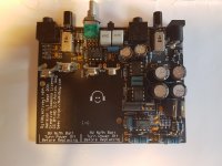
Here are the photos as you said. If they are not enough i can get more.
Well the orientation of chips is good i watched a lot of pictures of working amp only problem is if they are not inserted enough :/ Can you recognize from pictures?
Imgur: The most awesome images on the Internet
Well the orientation of chips is good i watched a lot of pictures of working amp only problem is if they are not inserted enough :/ Can you recognize from pictures?
Imgur: The most awesome images on the Internet
Attachments
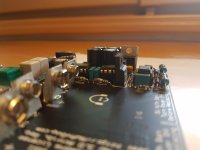
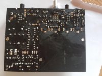
Do you think that they are fitted correctly? Imgur: The most awesome images on the Internet

Can that be repaired or will the heat damage components?
You can repair it (just resolder the connections): - remove the socketed ICs before you solder anything - give the board enough time to cool down between soldering, don't try and repair all the pads in one go
- Home
- Amplifiers
- Headphone Systems
- The Objective2 (O2) Headphone Amp DIY Project