It works perfectly now, thank you so much @agdr!!
Good deal!
")
FWIW Mouser just sent an email that the part image for the mosfet has been corrected, back in post 4376. Mouser is pretty good about responding to listing mistakes.
Hi!
The regulators are speced for quite high temperatures, so actually they are operating quite safely, although almost too hot to touch. The lowest recommended voltage (and probably the best compromise) is 14vac (500mA will be good), But actually you can even try 12vac adapters, as long as you don't use hungry cans. Many adapters deliver slightly higher voltages without load. Worst thing that can happen is regulators dropping out.
The regulators are speced for quite high temperatures, so actually they are operating quite safely, although almost too hot to touch. The lowest recommended voltage (and probably the best compromise) is 14vac (500mA will be good), But actually you can even try 12vac adapters, as long as you don't use hungry cans. Many adapters deliver slightly higher voltages without load. Worst thing that can happen is regulators dropping out.
The O2 is a bit hard on its regs unfortunately. No space for any real cooling (maybe you can find a way to clip on some sort of metal sheet), no protection diodes to aid in reverse current flow. I suspect the latter may have contributed to the odd negative reg failure. Maybe it's possible to squeeze in some 1N4001s underneath the board?
Hi Adgr,
I tried to replace the NJM2068 by 2xLME49990, and found that LME opamps just not suitable here.
First I noticed timbral change, much more noticable than expected from going from 0.001% to 0.0005% THD. The sound became just like sound of tube amp.
The first measurement I performed just by my finger - the temperature of opamp was about 50-60 C*. It's quite abnormal hot for opamp loaded to about 1.4K. Then I went to more advanced measurement - I used my DSO to see what's going on the LME49990 output. And as I expected, there was an oscillation. Small - less than 0.1V amplitude, but enough to impact the sound, and make the opamp hot to touch.
Of course I tried to add 1 0.22uF cap, or 2x0.22uF caps with middle connection grounded.
There was a very small change of amplitude of oscillations. I swapped LME opamps to 2068, and oscillations gone.
I returned an old pot and 40.2k resistors, and checked the circuit again - the result was same: LME49990 - hot, perfect sinusoidal 0.05-0.08V output, + tube like sound,
NJM2068D - cool package, neutral sound, almost flat output at no input signal.
Looks like that not impedance issue. It's like something altering the signal phase at high frequency. NJM eliminates that problem because it slow, while 110MHz LME49990 becomes an oscillator.
The O2 is a bit hard on its regs unfortunately. No space for any real cooling (maybe you can find a way to clip on some sort of metal sheet), no protection diodes to aid in reverse current flow.
You always can to build separate PSU, then to deliver the power to amp by screened 3 axial cable, or even screened twisted pair.
2Tolik all that looks like inproper caps on power rails or improper frequency compensation
So,
- If that 2x0.22uF were ceramic ones? Many film and all electrolytic caps are useless at MHz-s frequencies.
- Do you put them close as possible to opamp pins?
- Try to add 4.7pF ceramic just between 2&6 opamp pins. That will be effectively paralleled to O2's own 220pF frequency compensation caps, but afraid that inductance between opamp and that caps too high to work them correctly with that fast opamp used with adapter. If that will help - better to move that 220pF close to opamp instead of adding additional caps. However likely that 220pF are not best value for new opamp, but that should not cause oscillation - just produce more THD that it would be with optimal value.
- As last, try to insert ~470R resistor between opamp and VR, close possible to opamp itself.
Last edited:
Hi Adgr,
I tried to replace the NJM2068 by 2xLME49990, and found that LME opamps just not suitable here.
Hi! I'm curious, did you use the dual LME49990 adapter from "Frugalphile" on eBay? Those are the ones I've been using and so far haven't had any oscillation problems. I'm fairly sure he is using genuine chips. The properties of specific adaptor boards can make a difference too. His are fairly small surface area boards. If the adapter board is accidentally routing an input line too close to the corresponding output line that can also be trouble.
As it turns out an 0805-sized surface mount MLCC capacitor will fit just fine between the pins of those film 0.22uFs the O2 uses. I'm working on new O2 design with inverting stages and I've HF-bypassed all the 0.22uF films that way with 0805's between the pins. Or just solder an 0.01uf X7R leaded MLCC cap between the 0.22uF pins under the board. Like misterzu said those film caps may look like open circuits at the 110mHz the LME49990 can handle. The ceramics should do a better job at high frequency. Also definitely worth trying his suggestion of a MLCC ceramic soldered right to the power pins on the top of the adaptor board, if you haven't already.
If you would like to give a different chip a try, consider the LME49880. That is the FET-input cousin of the LME49990 which is also THD+N rated down to a 600 ohm load. I'm using that chip for the gain stage in my new creation.
Its GBP is only 25mHz, just a tad less than the 27Mhz of the orginal NJM2068 chip, much less of a turbocharged race car than the 110Mhz LME49990. Should be much less prone to HF oscillation. The LME49880 is a dual chip so you just need one on an approprate adapter board. It is a "power pad" chip with a metal bottom for heatsinking, but just driving the 5K pot it should be OK. If you happen to find an adapter with a power pad "pad" in the middle it should be tied to V-, pin 4 on the chip.But regardless you definitely have found a problem in your case! That is exactly what happens with chip oscillation, they heat right up like that. Good troubleshooting work.
Last edited:
A. He has 0 items for sale.Hi! I'm curious, did you use the dual LME49990 adapter from "Frugalphile" on eBay? :
B. For well known reasons I prefer to get the things like LME... AD... OPA... LT... etc. from here only. Most exactly from their local distributor, because of $10 shipping to my door.
C. The adapter - 1pcs SOIC Single to DIP8 Dual OpAmp Adaptor | eBay
looks to be OK.
Now the caps I used - B32529C224K - EPCOS - CAPACITOR PEN FILM, 0.22UF, 63V, 10%, RADIAL | Farnell element14
Looks fine too, but I have some 0808 ceramics to try and I'll do it.
But here is another thing that boring me - all ebay adapters I saw are just bad by design to my eyes. While coupling caps should to be placed so close as possible to an active device, those adapters just taking an IC from the decoupling caps away. And I think that this problem not far less, than film caps. By the way, I successfully dealt with HF issues in SMPS, by using snubbers with film caps.
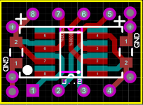
The "patches" still possible, but I'm not fan of that way. I prefer something more elegant. Below is adapter I developed to use in such situations.
It can to handle 4 x 0805 caps, + 2 tantalum, film, or electrolytic caps with 5 mm lead spacing.
If there is problem with gerbers RS274X, just PM, I'll do it in RS274D format.
Nope, I'll do it with LME49990, or I'll do a redesign of whole board for 49990+49600.If you would like to give a different chip a try,
Thank youGood troubleshooting work.
Once I played a lot with development of SMPS, so some experience still helps here. + US made Scope Attachments
Last edited:
Well, I added 3 0.1uF X7R. The one - just below U1 pins, and 2 across C17 C18 pins.
Also I was lucky enough to find the utility that can to get screenshots of my scope.
The pictures are better than any worlds...
Also I was lucky enough to find the utility that can to get screenshots of my scope.
The pictures are better than any worlds...
Attachments
Last edited:
A. He has 0 items for sale.
Here is the guy:
2pcs LME49990 Single DIP8 Adapters | eBay
sure enough, it looks like he only has these single adaptors up right now.
Hey that is great you are getting the real thing from Farnell! There are so many fakes out there.
If you haven't already you might want to check out opc's "Wire" headamp board, which is a LME49990 + LME49600. He has an AP tester and has published THD+N numbers on it:
http://www.diyaudio.com/forums/vend...jects-available-here-bal-bal-se-se-lpuhp.html
From your plot it looks like one cycle is about 10nS if I'm looking at that scale right, or 100Mhz, right up there at the max for the chip.
Not the fakes only. The ebay and alliexpress are just overloaded with QC filed parts, and the problem that no one climes about what's really wrong. If the pins of the opamp are 0.1 mm shorter, or marking is blur - it's could to be forgiven. But if the problem inside...There are so many fakes out there
I saw the Wire, it is a simple, but yet very high performance amp . I think I'll try to do some similar on the board, that fits O2 enclosure.
I saw in reality how rather fast opamp (opa211) oscillates just because of compensation capacitor was too far from it.
You may also simple short outputs and negative inputs with a short wires instead. That will force input stage to work at unity gain buffer and if it will be stable - its definitely something that can be fixed by playing with freq. compensation
You may also simple short outputs and negative inputs with a short wires instead. That will force input stage to work at unity gain buffer and if it will be stable - its definitely something that can be fixed by playing with freq. compensation
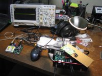
Tolik - I happened to have some test equipment out testing another amp. Here are some photos of an O2 with that Frugalphile dual LME49990 adapter.
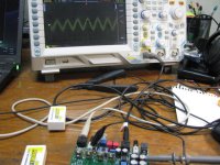
* The first photo is the test setup with destroy-able test headphones. That O2 on the left has the dual LME49990 adapter and standard NJM4556A output chips. It also has the 5K pot modification, with the 4.7uF coupling caps. It has one of my power management latch circuit boards in for U2, but that is out of the signal path (just controls the mosfets) and won't have any effect on these tests. I would remove it, but the board pins are hot-glued to the socket. The scope and probes are 200Mhz.
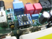
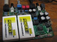
* The next two are just closeups of the board and that Frugalphile dual LME49990 adaptor.
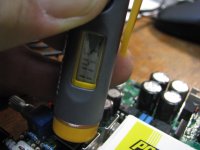
* The next one is the temperature reading on the adaptor topside chip. I get around 114.5F. This is with music going through the board. The O2's "on" LED shows just above the pot.
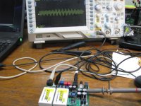
* Next is the base EMI noise level with batteries out of the O2 (no power of any kind applied to the O2), then the next is with the batteries installed and the O2 turned on. About the same. The "fuzz" around the signal is just triggering trouble, not an envelope of some kind.
This is all measured at the output of the NJM4556As, which will be frequency limited by those chips. I've also tried measuring at the pot with some series resistance tack-soldered in series, to keep the scope probe capacitance from causing any chips oscillations, and that measures the same.
* The first photo is the test setup with destroy-able test headphones. That O2 on the left has the dual LME49990 adapter and standard NJM4556A output chips. It also has the 5K pot modification, with the 4.7uF coupling caps. It has one of my power management latch circuit boards in for U2, but that is out of the signal path (just controls the mosfets) and won't have any effect on these tests. I would remove it, but the board pins are hot-glued to the socket. The scope and probes are 200Mhz.
* The next two are just closeups of the board and that Frugalphile dual LME49990 adaptor.
* The next one is the temperature reading on the adaptor topside chip. I get around 114.5F. This is with music going through the board. The O2's "on" LED shows just above the pot.
* Next is the base EMI noise level with batteries out of the O2 (no power of any kind applied to the O2), then the next is with the batteries installed and the O2 turned on. About the same. The "fuzz" around the signal is just triggering trouble, not an envelope of some kind.
This is all measured at the output of the NJM4556As, which will be frequency limited by those chips. I've also tried measuring at the pot with some series resistance tack-soldered in series, to keep the scope probe capacitance from causing any chips oscillations, and that measures the same.
Attachments
Last edited:
- Home
- Amplifiers
- Headphone Systems
- The Objective2 (O2) Headphone Amp DIY Project