To be seeing 23.7 between pins 4 and 8 means you must have measured that with it plugged into mains. That would push up the voltage on pin 2 as well.
(If you calculate it out the numbers agree. There would be approximately 23 volts on pin 7 of U2 which effectively places the 1.5meg across the 270k giving 229k approx.
So you have 229k and 33k in series (giving 262k). The current is 23.7/262000 which is 90microamps, and 90 microamps would develop 2.97 volts across the 33k. That is what are seeing on pin 2)
The current draw on the batteries should be approximately equal but batteries can vary one to another.
Have you tried going quite a bit lower with the 1.5meg ? and seeing if that stops the on/off behaviour when the batteries are running low ? You have to introduce enough hysteresis so that the comparator keeps the amp turned off, even if the battery voltage suddenly rises as the loading is removed.
Another way to check the comparator... if you connect your meter between pins 2 and 3 of U2 and watch the voltage as the battery discharges you should see pin 2 higher in voltage than pin 3 (a positive reading on the meter). As the batteries discharge the reading will fall toward zero and as soon as it crosses that zero point and becomes negative (so pin 3 is now positive with respect to pin 2) the amp should turn off.
It would also be instructive at that point to measure the total voltage of the two discharged batteries (so that's between B1+ and B2- (those points are marked on the diagram) and see what the reading is with the amp OFF (switch S1 turned OFF) and then with the amp on (S1 on). We could see then if there was a large jump in voltage as the batteries come off load.
That sounds good, and seems to confirm it was the battery voltage rising that was causing the circuit to flip back and forth. Remember you can alter R9 a bit (if needed) to trim the cut off point to a value that matches the true "fully discharged" point of the batteries.
The trouble with this part of the circuitry is that it depends on the exact characteristics of the LED (which is used as a voltage reference). If that voltage varies from device to device, then the circuit trip points vary between each O2 build.
Excellent")
The trouble with this part of the circuitry is that it depends on the exact characteristics of the LED (which is used as a voltage reference). If that voltage varies from device to device, then the circuit trip points vary between each O2 build.
Excellent
And after searching and searching all day through this thread, I can't quite seem to find a specific answer on how to fix my problem. I'll post as many details here as possible, and hope that Mooly or someone else can help me. Not my first DIY build, but I'm not great at the finer details of circuits and such so any help would be greatly appreciated.
I'm building a desktop version without batteries, and everything is populated on the board and soldered (100% sure) and there are no solder joints (99% sure), and everything is oriented in the correct direction (100% sure). I have a channel balance issue in which the sound is getting pulled left pretty heavily. It sounds like the right channel is not receiving the same voltage as the left, but I'm not sure how to find the culprit. Nothing is getting hot, nothing seems to be overtly incorrect. I have a feeling it is either U5/6 or Q1/2, but I'd also like to know how to test these individual pieces (if I can while they're in the board). I am sure that the top right foot of S1 is not touching the nearby via. I have gone through the checklist that Mooly made a number of pages back, and have found a couple errors, so I'm just going to post my measurements below. Any help on where to go from here would be greatly appreciated. With U2 installed and AC plugged in and the unit powered on, I get the following measurements in VDC:
D3 striped: +19.82
D4 striped: 0 <---- my main issue, I take it
D4 non-striped: -19.80
U3, Pin4: -11.72
U3, Pin 8: 11.66
U2, Pins 1-7: -11.72, 11.66, -11.71, -8.8, -10.04, -11.72, -10.04, -11.72, 8.28
D5 striped: -11.91
D5 non-striped: -11.73
D1 striped: 11.66
D1 non-striped: 11.85
R24: -11.73
Your voltages are fine. If you have -/+12 volts on the opamp supply pins then there is no issue there. Q1 and Q2 are just switches... so if the rails are up then they are not the problem. Checking the operation of the comparator and rail switching is covered in my link at the bottom of post #1
(D4 stripped end is AC so a reading of zero volts DC is correct)
Gain problems will almost certainly be down to the feedback components around U1. You wont have a faulty opamp.
There is a known issue of some part (is it the gain switch ?) shorting out to a via ? on the PCB.
http://www.diyaudio.com/forums/head...eadphone-amp-diy-project-202.html#post3992557
http://www.diyaudio.com/forums/head...eadphone-amp-diy-project-202.html#post3993087
I covered a problem with a gain issue here together with some pretty comprehensive tests you can do. If there is a gain difference somewhere then this will show it.
http://www.diyaudio.com/forums/head...eadphone-amp-diy-project-201.html#post3987672
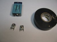
Sorry if this has been answered before, but the O2's female and male battery connectors are obsolete and not sold on digikey/mouser anymore. What are some good alternatives?
The alternates in his "notes" column work, Keystone 593 and Keystone 594 (Mouser #534-593 and #534-594).
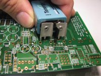
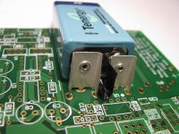
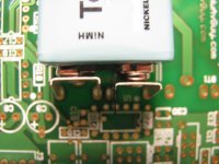
Also here a "pro-tip" on soldering in the battery connectors.
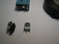
With the O2 power switch off, snap the terminals onto the battery first, then carefully put the terminal PC pins into the PCB holes. Putting a small piece of electrical tape on the inner edge of one terminal first is a good idea so it can't accidentally rotate and short out the battery against the other terminal before putting them in the holes. Then solder just the center and outer pins on each terminal, making sure the battery is still lined up straight with the PCB markings when you flip the board to solder the pins. Then remove the batteries and solder up the inner pins (the inner pins are a little too close together to risk soldering with the battery attached). The problem this solves is that one battery terminal has to mount just slightly forward of the other the way 9V battery terminals are constructed. It is nearly impossible to get that right unless the battery is attached.
Last edited:
The alternates in his "notes" column work, Keystone 593 and Keystone 594 (Mouser #534-593 and #534-594).
Also here a "pro-tip" on soldering in the battery connectors.
The problem this solves is that one battery terminal has to mount just slightly forward of the other the way 9V battery terminals are constructed. It is nearly impossible to get that right unless the battery is attached.
Alright, appreciate the help. Just want on a little bit clarification on "Putting a small piece of electrical tape on the inner edge of one terminal". I'm not sure I understand.
Alright, appreciate the help. Just want on a little bit clarification on "Putting a small piece of electrical tape on the inner edge of one terminal". I'm not sure I understand.
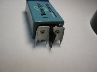
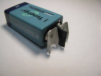
A picture is worth a thousand words, as they say.
In that last photo the difference in the amount forward between the two terminals really shows up. From the photo is looks like the battery just isn't pushed in all the way, but it is. The terminals in the photos are the Keystone terminals.
Attachments
Last edited:
Build a desktop version with the amp only without gain. Since I will be using with my PC so I will be using the software to control my gain. Using 2 5V DC adapter.
Results using 33 ohm load at 1mW.
THD+N 0.0008%
Noise -118dBV unweighted
Noise -120dBV A weighted
Crosstalk -84.5dB at jack output
DC offset 4.5mV
http://www.diyaudio.com/forums/attachment.php?attachmentid=441216&stc=1&d=1412149158
Results using 33 ohm load at 1mW.
THD+N 0.0008%
Noise -118dBV unweighted
Noise -120dBV A weighted
Crosstalk -84.5dB at jack output
DC offset 4.5mV
http://www.diyaudio.com/forums/attachment.php?attachmentid=441216&stc=1&d=1412149158
Attachments
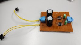
Gave some thought of it, in the end I decide not to use the PC supplies. O2 uses star ground topology, so if I use USB 5V for power and using the PC sound card line out, would get nasty ground loop problem.
Will try listening tonight. If I like it, may consider building a proper PCB with transformer on it.
Will try listening tonight. If I like it, may consider building a proper PCB with transformer on it.
Have a look at DC/DC convertors. You get a totally floating output, no ground loops.
I've picked this at random to give you an idea.
1PA0512S-WR - POWERPAX - 1W UNREG SIP SCP 5V IN / + - 12V | CPC From This Range
I've picked this at random to give you an idea.
1PA0512S-WR - POWERPAX - 1W UNREG SIP SCP 5V IN / + - 12V | CPC From This Range
Thanks for the link.
The DC-DC will work as long as I don't use the USB power. Like a single 5V adapter.
Once I use the USB for the DC-DC, the ground current will travel to both the USB ground and Line-out ground. Which adds noise.
Or the alternatives is to use USB audio then I am still in control of the grounding...
The DC-DC will work as long as I don't use the USB power. Like a single 5V adapter.
Once I use the USB for the DC-DC, the ground current will travel to both the USB ground and Line-out ground. Which adds noise.
Or the alternatives is to use USB audio then I am still in control of the grounding...
... Using 2 5V DC adapter.
http://www.diyaudio.com/forums/attachment.php?attachmentid=441216&stc=1&d=1412149158
Even if 1 adapter gets momentarily disconnected (tug/pull on the socket) - you will get DC at o/p. I suggest using O2 style power section with real gnd. You can ommit the low batt. protection FET circuit.
I have a newbie question about building an O2+ODAC. I'd like to make one which behaves more like a desktop DAC+amp+preamp, with RCA analog input jacks (for feeding the O2 by itself), the USB input jack from the ODAC, and a switch to select between the two inputs. In addition, I want RCA analog output jacks from the ODAC, which would ideally get signal regardless whether the O2 is in use or not.
Is this possible? I'm not well-versed in audio electronics, and hope to use this project as a learning experience. I had hoped that the changes I want would just be a matter of (1) using off-PCB jacks and soldering to connections on the PCB, and (2) splicing in some wires and switches. I'm worried, however, that this may not be possible for some reason, or the switches will cause signal surges down the signal chain, or some other unpleasantness.
Is this possible? I'm not well-versed in audio electronics, and hope to use this project as a learning experience. I had hoped that the changes I want would just be a matter of (1) using off-PCB jacks and soldering to connections on the PCB, and (2) splicing in some wires and switches. I'm worried, however, that this may not be possible for some reason, or the switches will cause signal surges down the signal chain, or some other unpleasantness.
- Home
- Amplifiers
- Headphone Systems
- The Objective2 (O2) Headphone Amp DIY Project