Channel Imbalance?
Hi everybody, I'd like to requisition a little bit of help from you guys!
I've just recently finished a build of the O2. I've tested all the DC/resistance as per NwAvGuy's DMM measurement charts.
With the audio, my left channel seems perfect, but I'm getting a right channel imbalance. Specifically, higher end treble and vocals. Instruments and percussion seem to come through fine. Does this count as a channel imbalance?
Either way I can't see a short on S2, I've checked the resistor pairs in circuit and they all have equivalent matching resistance. Although I found that R14 R20 were about 900ohms while the charts listed 100-300ohms. Everything else was as expected and within given ranges for VDC and resistance.
I've also switched U3 U4 around with no difference so I think the ICs are good.
Beyond that, I don't think I have a soldering issue as went through them again so I'm rather stumped. Would you have any suggestions for me?
Thank you for your help!
Although I found that R14 R20 were about 900ohms while the charts listed 100-300ohms.
Sorry, that should be 9000ohms.
You can not measure resistors in circuit and in any event its most unlikely any are faulty.
Suspicion of problems with level and response need a scope and signal source to test properly.
Without these the best you can do is a process of elimination and basic tests. A basic test of gain using a DVM is here. If you apply the same voltage to both inputs simultaneously then you can check for gain imbalance.
http://www.diyaudio.com/forums/head...eadphone-amp-diy-project-201.html#post3988791
Is the volume control tracking properly ? Check the DC voltage on the wipers of the pots and the final opamp outputs at different levels if you do a DC gain test.
Any tonal imbalance can only be down to either the headphones (it happens) or an incorrect value for the 220pf and 2.2uf coupling caps. Nothing else can affect the frequency response as long as the resistors fitted are the correct value.
Thanks Mooly.
I know the headphones are good thankfully because I've been using them for the last month prior to this with my friend's cmoy and straight out of source. Tested them again after the testing just to make sure after the paranoia set in!
I've run through the stuff you mentioned in your linked post.
I've verified U1 and the pot are equal for L/R inputs, following through the circuits until C13/C14 where they both cut off at the second leg.
After that I can't seem to get any VDC readings for either L or R through to output, so I assume I'm doing something wrong here?
After listening through the circuit again, I can hear a loss as well as an interesting lagging effect of the bass in the R channel as well as loss of treble as I described earlier. Would this confirm a failure of the R channel capacitors? Ie. C19 or C13?
Thanks again!
Testing up to C13 and C14 is proved OK. You have the same levels.
The two caps block DC so what you can do is link both caps out. The final opamps will (should) then give an identical voltage on their outputs that is the same as the voltage on the pot wiper.
Could you have a problem with the headphone socket ? If there was a problem with the common ground connection to the 'phones it would all sound a bit weird and phasey.
I doubt there is a problem with the caps... to test though it will still all work with those caps linked out... but the response then goes down to DC.
Oh wow, yeah it's the output socket. I'm using the 1/4" neutrik jack, but when I slotted in a spare 1/8" jack I had the audio works perfectly even without soldering it in.
I replaced and resoldered the wire on both ends, P2 and the jack itself.
I must be doing something elementary wrong, as when I move balance to the right I get regular RHS mono, left gives a centre balanced mono sound and centre gives that odd LHS bias from before. I don't see any shorts or anything like that so I'm highly confused.
I'm using pins 2/3/4 as G/L/R.
P.S. VDC and caps.. derp! The logic connected after I saw your post.
Out of curiosity, when you mentioned linking the caps, do you mean shorting the legs to bypass them?
Last edited:
That's great so a problem with the socket.
Not quite following you on the "balance" thing and when you say you move balance to the right etc... the O2 doesn't have a balance control AFAIK. (I just work from the circuit diagram... I never built one, never heard one and never seen one)
Yep, the caps could be shorted out (legs linked together) as a test but then the amp would have a response down to DC which isn't good really and it can also make the volume control operation a little noisy and scratchy due to the small bias current that would then flow out of the opamp inputs and into the pot wiper.
so a problem with the socket.Not quite following you on the "balance" thing and when you say you move balance to the right etc... the O2 doesn't have a balance control AFAIK. (I just work from the circuit diagram... I never built one, never heard one and never seen one)
Yep, the caps could be shorted out (legs linked together) as a test but then the amp would have a response down to DC which isn't good really and it can also make the volume control operation a little noisy and scratchy due to the small bias current that would then flow out of the opamp inputs and into the pot wiper.
Sorry, I meant as in balance controls from source (i.e computer).
Anyway now I know where the issue is, I'll be able to actually do something about it. As you said, I probably mixed up ground or something. I'll revise the charts for audio jacks.
Thanks for your help Mooly! You must be wise indeed to troubleshoot something you've never seen before
Anyway now I know where the issue is, I'll be able to actually do something about it. As you said, I probably mixed up ground or something. I'll revise the charts for audio jacks.
Thanks for your help Mooly! You must be wise indeed to troubleshoot something you've never seen before
Thanks OK (I haven't got all the answers though )
Yep, get your headphone ground and channels sorted first. That's easy to test just by applying a signal to only the left or right input (only as in only one connection, and not a stereo feed that relies on an upstream balance control. Just one input plugged into one RCA socket. Leave the other open). That will confirm the output is OK.
Then check your input wiring. The same issues can occur if a ground is floating there, you get sound but its phasey and weird and would not respond correctly to a balance control.
(I haven't got all the answers though )Yep, get your headphone ground and channels sorted first. That's easy to test just by applying a signal to only the left or right input (only as in only one connection, and not a stereo feed that relies on an upstream balance control. Just one input plugged into one RCA socket. Leave the other open). That will confirm the output is OK.
Then check your input wiring. The same issues can occur if a ground is floating there, you get sound but its phasey and weird and would not respond correctly to a balance control.
I did build RCA jacks into it, but I don't have actual RCA output, it was more a potential futureproofing thing.
First things first, took out the P2 wiring, checked for shorts/poor solder joints and without soldering I tested it with the 1/8" into J3, worked as expected as before.
With an analog input into J2 and seperately with ODAC to P1, upstream balance worked as expected and so did music.
Soldered new wires into P2 with headphone jack, tested again with 1/4" jack and same unbalanced/phased results as before. With P2 soldered in and the 1/8" dropped in, the 1/8" still sounds fine. Can't see any shorts on the jack itself or any soldering issues. It's driving me nuts, if J3 and P2 are directly linked as I can see from the board traces I don't see what the disrepancy is coming from.
I did try to run a battery across the RCA terminals, but that didn't work particularly well, got static on one ear, both ears randomly both with J3 and P2. In hindsight the dodgy J3 results might have been because I didn't check the seating of the jack. I'll have to find myself a 3.5mm to RCA adapter.
Last edited:
With an analog input into J2 and seperately with ODAC to P1, upstream balance worked as expected and so did music.
Is that "worked as expected" (as in all good), or "worked as expected" (no change... still faulty... thought it would be...)Why don't you make a test track using something like Audacity,
http://www.diyaudio.com/forums/soft...ing-using-audacity-get-you-started-guide.html
and make it with a left only and then a right only channel. Use a lowish frequency (say 400Hz) and a lowish level. That's much better than music and will allow you to see/hear where any channel problems are.
It does sound like your problems are related to the sockets/wiring but knowing exactly what is the problem is difficult.
Ah, as a replacement for the RCA? I'll take a look at that soon, probably the weekend. Hopefully I'll be able to get more info! Works as expected, as in the 1/8" within the J3 sounded perfect, stereo separation and clear as crystal. Makes it all the more frustrating. Thanks again Mooly!
Yeah after testing, it's pretty much as I described earlier.
Centre - LHS sound only
Left - gives both channels
Right - RHS sound only
If I put balance at somewhere around 40% I seem to get the noise to give equal channels, but it somehow sounds different from if I use pure LHS balance.
I figured this meant that I must've fudged the L/G wires. Redid my assumptions for the socket and realised that I was doing the whole thing backwards the whole time (and multiple times!), which was why R still worked. Essentially I was wiring the tip as ground and sleeve as left.
I'm so embarrassed. :<
I guess after troubleshooting the entire amp for such an elementary mistake I mostly know how and why the amp works, which I guess is a bonus.
Thanks for all the help and sorry for wasting all your time Mooly, but we got there in the end!
So I have been curious to try 3x LME49720HA (the metal can versions) in my official O2 build and it's picking RFI like mad.
But when I use 3x LME49720HA (DIP package) instead, there's no RFI.
Shouldn't the TO-99 be better than DIP package?
How can one make TO-99 opamps don't pick RFI at all?
Just my 2 cents...
But when I use 3x LME49720HA (DIP package) instead, there's no RFI.
Shouldn't the TO-99 be better than DIP package?
How can one make TO-99 opamps don't pick RFI at all?
Just my 2 cents...
Have you scoped the opamp outputs to see what is going on ? It may be unstable.
Well it probably is in some way unstable, but if it's only the TO-99 package causing it, that's a mystery to me. No soldering of TO-99 to some adapter either, it is directly put with its pin legs to O2's DIP sockets... But no problems with DIP package of this same opamp here - no cellphone clicks, beeps, buzzing, modulating noise, etc...
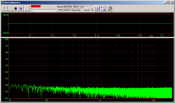
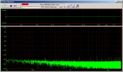
I wish I had some Audio Precision/dScope
, because all I can measure right now is higher noise floor with some harmonics than the noise floor of my RME A/D converter - however with LME49720MA DIP package the noise floor blurs with the RME A/D converter's noise floor...Do TO-99 opamps require some special care in this particular O2 design?
This is just for curiosity sake, if this doesn't get solved I'll stick again to my favorite opamp
PS: I have also successfully tried NE5532, NE5534, LME49990 (all in plastic packaging) and they don't exhibit this behavior...
Attachments
- Home
- Amplifiers
- Headphone Systems
- The Objective2 (O2) Headphone Amp DIY Project