and primary voltages from the left and the right leg of the bridge showing phase shift modulation.
Well, I do not need a lecture on defficiencies of class BD modulation in the proposed circuit, but leakage inductance is the last one that makes this circuit unpractical to build.
Best regards,
Jaka Racman
Well, I do not need a lecture on defficiencies of class BD modulation in the proposed circuit, but leakage inductance is the last one that makes this circuit unpractical to build.
Best regards,
Jaka Racman
Attachments
You should apply a full duty cycle square wave to the primary of the transformer, and use another full duty cycle square wave to drive the gates of the bidirectional switches in the secondary side. Then, modulation is achieved by shifting these two waves. Currently you are applying phase shift between both halves of the primary side full bridge, and synchronizing the bidirectional switches with one of the halves.
Also, all the spikes shown are due to transformer leakage inductance as I pointed out previously. A spike is produced every time transformer current has to be reversed, and that happens exactly every time the bidirectional switches (or synchronous rectifiers if you prefer) toggle.
The last plot shows how spike amplitude and width follow output current magnitude, as the higher the current, the more energy stored in leakage inductance and the more voltage and time required for proper resetting.
And finally, you don't expect a simulator to produce accurate spikes, do you? Note that PSPICE engine does not natively support variable MOSFET capacitances and most library models don't use complex subcircuits to model them either. Obviously capacitance is damping the spikes but in an unrealistic way.
Jaka!
If a spike doesn't reach avalanche voltage, it doesn't mean that there is no loss. Inductive energy can't be disappear, and there is no way to return to DC rails.
Fredos circuit is significantly different. For example it is unusable for that kind of modulation you showed.
If a spike doesn't reach avalanche voltage, it doesn't mean that there is no loss. Inductive energy can't be disappear, and there is no way to return to DC rails.
Fredos circuit is significantly different. For example it is unusable for that kind of modulation you showed.
Eva, you are guilty of the same sin as I. I did not check Fredos schematcs before i posted the link to the patent application but interpreted his cryptic description my way knowing that he uses BD modulation in his other designs. Shematics posted clearly indicate classic phase shift modulation betwen the primary and the secondary as in the old US patent that I posted.
On the other hand, you did not check the link that I posted. I am glad that you now understand how the circuit from the patent application operates and why leakage inductance is manageable in this type of the circuit.
And yes, I trust spice analysis more than "a prima vista" (non)educated guesses. I am also aware about the limitations of various Spice simulators using them for more than 15 years. I could not care less about PSPICE since they have never got past the 2G6 engine IIRC. On the other hand LT Spice can use nonlinear capacitance model and Si4490DY is modelled as such. This is why LT Spice it is called Switcher CAD.
Best regards,
Jaka Racman
And yes, I trust spice analysis more than
But does it really say that no loss due inductance? I don't think so! Much more detailed simulation is required to decide about it, but theoretically there must be loss.
At your example it is manageable, but think of it at 2000 W output, and without heat sink!
Pafi, of course there is loss as in every inductive turn off unless you use snubbers. But as an excercise you can calculate stored energy in the leakage inductance and multiply it with the switching frequency. In the example shown Spice calculated 2.23uJ of energy loss in the largest spike which is even more than the actual energy stored in the leakage inductance.
Best regards,
Jaka Racman
Best regards,
Jaka Racman
Attachments
Just remember that in symetrical switching like this, you will clamp overshoot ''naturaly''...When a side switch, coupling in inductor reflect the same overshoot on the other leg and because ''rectification'' is done in symetrical way, over shoot is clamped and feeded as power to load...That's what my experimentation give...Not simulation! Prototype is working well, except soem ''harsh'' sound when playing music...
Fredos
www.d-amp.com
Fredos
www.d-amp.com
Who said that getting some sound from a switching circuit was difficult?
Indeed, getting sound is very easy even at high powers, the difficult part is to make it CLEAN.
I could scale the prototype in which I'm now working to 2400W right now by increasing supply rails and changing the inductor and some capacitors, but I'm not satisfied with the common mode switching spikes being radiated by wiring, that show up in my oscilloscope probes as up to 60mVp-p with three or four periods of ringing at high powers.
I want it QUIET as that:
(which I suppose to be the output ripple of an UCD400).
(Image taken from http://www.audioholics.com/techtips/audioprinciples/amplifiers/SwitchingAmplifierBasics2.php )
Indeed, getting sound is very easy even at high powers, the difficult part is to make it CLEAN.
I could scale the prototype in which I'm now working to 2400W right now by increasing supply rails and changing the inductor and some capacitors, but I'm not satisfied with the common mode switching spikes being radiated by wiring, that show up in my oscilloscope probes as up to 60mVp-p with three or four periods of ringing at high powers.
I want it QUIET as that:
An externally hosted image should be here but it was not working when we last tested it.
(which I suppose to be the output ripple of an UCD400).
(Image taken from http://www.audioholics.com/techtips/audioprinciples/amplifiers/SwitchingAmplifierBasics2.php )
analogspiceman said:I am confused about the topology under discussion. Does its final output consist of (nearly) fifty percent duty cycle square waves differenced against each other where their relative phase shift is the control means or is it something else?
Same here, possibly with BD modulation ? That is what I got out of it.
A full duty cycle square wave is always applied to the primary of the transformer.
The bidirectional switches decide with which polarity the square wave obtained in the secondary side is applied to the output inductor.
The polarity is toggled at the same frequency of the primary square wave clock, but with an adjustable delay that in turn decides the duty cycle as seen by the inductor.
It can be also operated in class BD with a phase shifted full bridge in the primary side, but that should result in rather clumsy performance.
Attachments
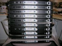
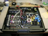
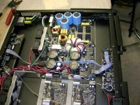
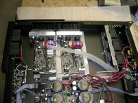
That's the only (cheap!) way to get a good airflow ina 1U case Eva!
Dont forget I push a 3kW continuous power for 15 minutes with this unit and at 1\3 of maximum power for 8 hours, parts begin to get warm...
Another reason, 2 fans can go off without thermal triping...So long term reliability is improved!
Fredos
www.d-amp.com
Dont forget I push a 3kW continuous power for 15 minutes with this unit and at 1\3 of maximum power for 8 hours, parts begin to get warm...
Another reason, 2 fans can go off without thermal triping...So long term reliability is improved!
Fredos
www.d-amp.com
3KW? Where? 
1500W rms per channel requires +-80V supply rails and output inductors rated in excess of 40A (not only due to heating but due to saturation!!). Furthermore, the secondary side windings and diodes of the SMPS transformer are also required to be rated at 40A rms. Of course, everything is rated at less than half that current (not to mention that a mains isolation transformer wound with standard hookup wire is not likely to get any safety certification, so you will face a big lawsuit if one of these wires ever melts and somebody results shocked or injured).
Furthermore, in order to get +-80V supply rails with your 30:7 transformer, 350V DC of rectified mains are required in the primary side (counting diode and IGBT losses), which can only be obtained with a mains supply above 250V AC!! All that not accounting for voltage drop due to mains rectification ripple.
Be serious, don't make us laugh (well, make us laugh if you want )
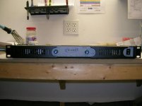
What the pictures show, rated in standard terms, is a 2x300W rms into 8 ohm and 2x500W rms into 4 ohm amplifier.
1500W rms per channel requires +-80V supply rails and output inductors rated in excess of 40A (not only due to heating but due to saturation!!). Furthermore, the secondary side windings and diodes of the SMPS transformer are also required to be rated at 40A rms. Of course, everything is rated at less than half that current (not to mention that a mains isolation transformer wound with standard hookup wire is not likely to get any safety certification, so you will face a big lawsuit if one of these wires ever melts and somebody results shocked or injured).
Furthermore, in order to get +-80V supply rails with your 30:7 transformer, 350V DC of rectified mains are required in the primary side (counting diode and IGBT losses), which can only be obtained with a mains supply above 250V AC!! All that not accounting for voltage drop due to mains rectification ripple.
Be serious, don't make us laugh (well, make us laugh if you want
)What the pictures show, rated in standard terms, is a 2x300W rms into 8 ohm and 2x500W rms into 4 ohm amplifier.
Hi,
Fredos, could us see your current draw picture? Since some people will wonder how that 'tiny' transformer able to produce 3000W power output.
Very good job anyway.
Comment for the mechanical design:
1. The heatshink fins are vertical, but your air flow are horizontal
2. Placing the fans at rear directly, not inside will more effective
3. It is a common design for PA Amplifier that the volume control must safe from any accident on stage.
- Status
- This old topic is closed. If you want to reopen this topic, contact a moderator using the "Report Post" button.
- Home
- Vendor's Bazaar
- The news D-Amp DLS3000....