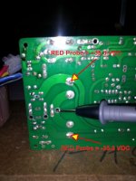
On C3 you should measure +35V and on C8 -35V (refer to PGND or internal leads of C3 and C8).
After removing pins you can clean with solderwick or better with a desoldering vacuum pump.
Clave I've never had much joy using de-soldering pumps. Maybe my model was rubbish. What make/model are you using?
OK, I have three LM3886 to try. They were all pulled but I might luck out. If not, I have other stuff to get from Mouser tomorrow and will ad some to the order.
Check R11 in-circuit, it should read about 1 ohm (almost a short). Check the Howland network resistors - the brown NOS RN55Ds that I originally included were a bit delicate due to their non-magnetic brass end-caps. Dale CMF-55s are more rugged, but magnetic.
If all is OK with the resistors, remove and install a new LM3886 - it puts less stress on the pads than installing a pulled LM3886 that may turn out to be bad again, and replaced again.
Clave I've never had much joy using de-soldering pumps. Maybe my model was rubbish. What make/model are you using?
I've always found desoldering pumps better than solder wick... but it's two year that I'm using a desoldering station, the best 100€ I never spent...
")
Desoldering pumps works better when the hole is larger than leads, I've had nice results with this one.
If I remember correctly, about a year ago Andrew posted a very simple circuit/device that looked like it could be modified to serve as a LM3886 test bed. I don't think there was any followup. Might be a useful project to develop.
I printed out a full 8 X 11" image of the silk but couldn't find one with V values listed. Is there one out there? Many of the discrete amps have a black and white line schematic with reference numbers.
The clip/pull/braid method worked OK. Lifted just one corner of one pad, but it was just on a top pad where the actual connection/trace is on the bottom of the board. I should have a pump by now, and need a better S Station. You might get a laugh out of my hole cleaning method but it works. I have a dozen or so surplus wire wound resistors with strong leads. I use a big 45 W iron to heat just the lead, push it gently through the hole and draw the solder out over the full length of the wire. The solder can be removed from the resistor with some sandpaper and the pieces can be used again. Not professional but functional.
Siva, didn't you say something in the 200s could be used at R14 for trouble shooting? I seem to remember that. What's best? Since I have an order going in today, and the partial trace lifted, I'll hold off till the new chips arrive. I'll get back to it this weekend.
BTW - Since these are down and the FEs are out on review (kind of - shipping was a disaster), I'm listening to my back-up, back-up amps - - BrianGTs with Uriah's Resistor Replacer. Still a very good price/performance winner in the chip world.
Attachments
Last edited:
I've always found desoldering pumps better than solder wick... but it's two year that I'm using a desoldering station, the best 100€ I never spent...
Desoldering pumps works better when the hole is larger than leads, I've had nice results with this one.
Thanks Clave
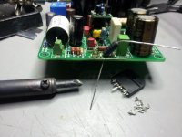
Check out the Russian K73-16B PETP axials. They're very good value at less than a dollar each depending on the value - I've tried the1.8 uF, but everything up to about 10uF seems to be available. They have excellent timbral balance, smoothness, and the microdetail is polished over with fine emory paper - no roughness. Here's a pic to show the approximate dimensions - this is in a MiniRef 1875, but I see no problems in a MyRef except that the leads may have to be bent below the body on both sides. They're rated at 5% tolerance, but it's easy to match them to within 1% from a lot of 10-20.
I didn't see your post ! Thanks! I was talking about using K75 bypassed with FT-1 in FE thread, I have also read some good reviews about k75, it seems to be a nice solution. The only problem is the length of this cap, 52mm... I can put it under PCB but actually is more simple to fit k73 on the board.
But I came across your LF01 just yesterday ! And I see that Bob is using it in his My-ref C. Do you still sell LF01 for My-ref C ?
It would be fun to buy K75, FT1, K73 and LF01 and playing with them, but I prefer to do a step by step tweaking. The goal is to eliminate a bit of harsh in the high frequencies.
I
But I came across your LF01 just yesterday ! And I see that Bob is using it in his My-ref C. Do you still sell LF01 for My-ref C ?
It would be fun to buy K75, FT1, K73 and LF01 and playing with them, but I prefer to do a step by step tweaking. The goal is to eliminate a bit of harsh in the high frequencies.
The LF01 has been replaced by the LF07 Class-A current booster (with the Diamond Cascode push-pull output stage). The effect on audible sonics is very similar to the LF01, i.e. Class-A sonics, which is no surprise because both use an LM318M with Class-A current booster. The main advantage of the LF07 is that it is very compact (~12mm x 12mm) and will fit comfortably in builds where the LF01 interfered with adjacent components due to its size.
There is also the LF03s, which is a fully-discrete DIP8 replacement for the DIP8 single opamps like the LM318. It has even better sonics than the LF01 and LF07, but it is barely stable in some MyRef Rev C builds and I'm still tweaking it for stability (this is very specific to the MyRef compensation, where a lot of high-performance opamps like the LME49710, OPA627, LT1028, etc. are unstable).
The dual version, called the LF03d, is usable for a variety of small-signal to line-level applications I/V converters, line amps, filters, etc. as an upgrade to monolithics in CDPs, DVDPs, DACs, etc. The LF03 has worked fine in just about any dual DIP8 upgrade that I've done, with rails ranging from +/- 4V to +/-15V - it just needs sufficient current (~15 mA per channel) to keep it happy.
Need some other ideas. Any more readings I can take????
Did you already re-measured DC offset between OUT and PGND?
Did you try a different LM318?
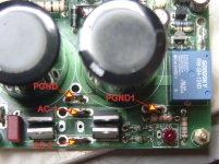
Dario, I'm still not sure I know the right place to use for PGNG as all four tabs receive power directly from the transformer on Siva's 1.3 boards. Is there a better spot to use?
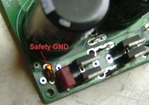
There is a "Safety GND" in the lower left corner.
EDIT: I just tested an LM318 in the other amp - it worked fine. The same piece makes no difference on the troubled build.
There is a "Safety GND" in the lower left corner.
EDIT: I just tested an LM318 in the other amp - it worked fine. The same piece makes no difference on the troubled build.
Attachments
Last edited:
Dario, I'm still not sure I know the right place to use for PGNG as all four tabs receive power directly from the transformer on Siva's 1.3 boards. Is there a better spot to use?
Both PGND and PGND1 are fine.
EDIT: I just tested an LM318 in the other amp - it worked fine. The same piece makes no difference on the troubled build.
Did you measure zeners?
Did you checked the 1R resistor as Siva's suggested?
Need some other ideas. Any more readings I can take????
Bob, remove the board and measure all the values of the passives (resistors and capacitors) in-circuit and compare them with the working board - if there's a significant mismatch in any value, please post the part designator and value here. Check R11 for sure, if you haven't already done so. R14 seems to be 470R on your board, I've been using (and supplying) 180R/1W for a while now without problems - something like 220R/1W should be OK too.
PGND & PGND1 are both on the same net (i.e. shorted) on the PCB - they're fine for the trafo connections.
Last edited:
Post 1752 shows a secondary AC lead tied to the PGND1...
I was wondering why he had them tied together in the terminal strip...
He has two secondary windings of 0-24, 0-24 (or similar). The connection looks OK, but the phasing of the two secondaries needs to be checked.
I'm just offering advice, take it or leave it, but unless there is something going on UNDER the terminal strip he has a blue wire going to the AC tab with a black wire going to the PGND1 tab TIED TOGETHER in the terminal strip.
Might be an optical illusion or there might be something under the terminal strip.. Does the black lead loop around under the terminal strip? If neither there is a problem there.
Might be an optical illusion or there might be something under the terminal strip.. Does the black lead loop around under the terminal strip? If neither there is a problem there.
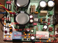
This is what I have so far. Tell me where else to probe.
After about 10 minutes to do these readings - the LM3886 is still at room temps. Apparently no power getting through.
Siva, do you have a silk screen of the V1.3 available?
After about 10 minutes to do these readings - the LM3886 is still at room temps. Apparently no power getting through.
Siva, do you have a silk screen of the V1.3 available?
Attachments
Last edited:
This is what I have so far. Tell me where else to probe.
After about 10 minutes to do these readings - the LM3886 is still at room temps. Apparently no power getting through.
Siva, do you have a silk screen of the V1.3 available?
OK - I'm not sure about this, but the reading across R14 looks a bit strange. You may want to replace it with a 180R/1W, and bend it out of the way of the PGND1 connector (to eliminate a possible short).
I'll dig out the silk screen (or export it from the layout) later today.
- Home
- Amplifiers
- Chip Amps
- The new "My Ref" Rev C thread