In a shop I have found SCR SY 1uf, polypropylene with tin foils, for 9$ (6,50 euro).
Do you think it is an interesting cap to try in rev C as C13-29 ?
Do you think it is an interesting cap to try in rev C as C13-29 ?
Attachments
Last edited:
Then I tried R42 = 270ohm and...no noise at all
Interesting
In a shop I have found SCR SY 1uf, polypropylene with tin foils, for 9$ (6,50 euro).
Do you think it is an interesting cap to try in rev C as C13-29 ?
Absolutely, they should be similar to Mundorf Zn (extremely detailed but a bit hard, though)
Absolutely, they should be similar to Mundorf Zn (extremely detailed but a bit hard, though)
... mmmh, I would prefer something smooth than extremely detailed. Otherwise they have this one, a metallized polypropylene MKP. But now I have Evox Rifa, maybe it's wasted time to replace them with a SCR that costs only 2 euro...
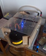
Anyway, that's for now my high class case, the worst ever seen
Attachments
HELP, my relay is backwards.
One of the V1.3 builds developed a power-on problem. The LED doesn't light and when the power is removed - after a 1-2 second delay - the relay clicks and the LED blinks lightly. One MUR820G diode had a lead that was failing so it was repaired and soldered. I replaced the relay but the same things is happening. Both modules have been working fine for months with Siva's LF0-1 add-on units.
Any Ideas???
Last edited:
HELP, my relay is backwards.
One of the V1.3 builds developed a power-on problem. The LED doesn't light and when the power is removed - after a 1-2 second delay - the relay clicks and the LED blinks lightly. One MUR820G diode had a lead that was failing so it was repaired and soldered. I replaced the relay but the same things is happening. Both modules have been working fine for months with Siva's LF0-1 add-on units.
Any Ideas???
Had similar symptom in one of my channels when i connected V+ to GND and vice versa. Short led blink for 2 secs and relay click (not always) after power off. Turned out that LM3886 was fried .Replaced them and everything works ok now. Hope you can get away without having to replace the amp IC's
It wasn't a hook-up problem. Both channels were operating fine - I was listening to music - and one side just went out like a light bulb. No smoke or spark, just silence. Both LF0-1 modules work fine in the good V1.3.
Just bought a new roll of desoldering braid, but I'm hoping I don't have to use it on the LM3886. Dario or Siva may have some suggestions for voltage checks and such.
Just bought a new roll of desoldering braid, but I'm hoping I don't have to use it on the LM3886. Dario or Siva may have some suggestions for voltage checks and such.
Any Ideas???
I've just had a very similar problem and it was, probably a bad solder joint on C15 (the little 22uf cap), I've simple touched it and started working again.
So, just to rule out the protection circuitry measure DC offset between OUT and PGND, if it's low as usual (less than 20mV) try to connect you speaker (-) to PGND, if you get good sound the culprit is the protection circuitry, if not further investigation is needed.
... I would prefer something smooth than extremely detailed.
Check out the Russian K73-16B PETP axials. They're very good value at less than a dollar each depending on the value - I've tried the1.8 uF, but everything up to about 10uF seems to be available. They have excellent timbral balance, smoothness, and the microdetail is polished over with fine emory paper - no roughness. Here's a pic to show the approximate dimensions - this is in a MiniRef 1875, but I see no problems in a MyRef except that the leads may have to be bent below the body on both sides. They're rated at 5% tolerance, but it's easy to match them to within 1% from a lot of 10-20.
Attachments
Just bought a new roll of desoldering braid, but I'm hoping I don't have to use it on the LM3886. Dario or Siva may have some suggestions for voltage checks and such.
Hi Bob, check with an LM318 or TL071 in the bad board. If it works, then the LF01 is marginal. If it doesn't work, check R11 - the 1-ohm lift resistor. Replace R11 if open or out of spec (say more than +/- 20%). If things are still not working, further debugging is needed before you attempt to replace the LM3886TF - which is a pain.
Also, there's a PCB trace that goes very close to the heatsink on the V1.3 board. Try covering this trace and the edge of the board with a layer of insulating tape to avoid the possibility of a short to ground (it probably doesn't damage anything, but it's best to exclude the possibility).
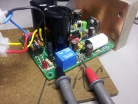
May be going from bad to worse. Pulled a via on one of the relay pads that caries power to the top of the board. No way to tell if there is full continuity, but I suspect so as the relay still clicks and the LED blinks quickly ~ 1-2 seconds after power is removed. It looks like the caps are charging - bulb tester glows and then goes out as it should. So it appears the protection system tries to - or is responding on the discharge phase.
The DC across the speaker terminals starts at +120 mV and floats down to - 70 mV and beyond after ~ 15 seconds. Don't mnow how far it will go.
There is no audible activity with ear to the speaker at power on or off.
The Pgnd to out is reading 33 V - not mV. Pgnd is used by a transformer lead as opposed to a separate/optional pad on the FE. Don't know if that is significant or the best spot to get that reading.
Inserting a LM318 makes no difference and both LFO-1 modules still operate as they should on the good V1.3 build.
I can fit a piece of stock paper between the amp and the HS along the full width, so there is a sufficient gap there.
Attachments
The Pgnd to out is reading 33 V - not mV. Pgnd is used by a transformer lead as opposed to a separate/optional pad on the FE. Don't know if that is significant or the best spot to get that reading.
The good news is that your protection circuit most probably worked like it should, and opened the speaker circuit. The speaker output is stuck at one of the rails, which would have been really bad for the speaker (if not protected).
Check R11 and replace if it's open/high resistance. Then measure all the rails - +/- 33V, +/- 12V to check that they're in spec. Re-flow the solder on the DIP8 socket if there's any doubt.
If the rails are out of spec, check the rectifiers to see if any one of them is shorted, especially the one with the broken lead or its immediate vicinity.
Edit: Check the wiring/phasing on the 0-24, 0-24 trafo leads also.
Last edited:
No luck yet.
1. Verified R23 @6K8 - off board - put back in
2. R14 read 260 ohm off board - replaced with 470 ohm 1/2W
3. Reheated all pads
4. Tried 4 different LM318s - same behavior - but not as strong a click and LED flicker
5. Re-mounted LF0-1
6. Replaced one power diode - same behavior
I thought I had a new set of diodes but only found 5 that had been pulled. Is there a method to test them out of circuit?
That a shame. The only way I know of to test a diode is to check resistance both directions then compare the readings to a new one. This doesn't give an under load conditions test though. I suppose you could make up a diode bridge out of them and place it under load, then take your readings. I found diodes to be pretty hard to destroy without leaving signs of distress/scorching on their case. Did you set up the board alongside the working one and take comparison measurements all the way through? That's the only way I can think of to nail the fault down to a specific area.
Good luck, hope you get this sorted soon.
Good luck, hope you get this sorted soon.
I thought I had a new set of diodes but only found 5 that had been pulled. Is there a method to test them out of circuit?
Measure voltage on big smoothing caps if you have +35V and -35V diodes are probably fine.
35.2 on both caps. What about Q1 -2 -3 ?
On C3 you should measure +35V and on C8 -35V (refer to PGND or internal leads of C3 and C8).
Polarities you've measured are correct? If so rectifiers are probably fine.
Since you have DC on output Q1, Q2 and Q3 are the last thing to think about, they're also probably fine.
The broken part is the LM3886, IMHO.
For an easy removal simply cut pins from case, heat each pad and with pliers pull off pins.
After removing pins you can clean with solderwick or better with a desoldering vacuum pump.
- Home
- Amplifiers
- Chip Amps
- The new "My Ref" Rev C thread