Speaking of noise... I do have a problem
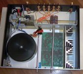
So, I finally (last week) got everything into a case with all the hole drilling etc. I am using the same case that Dario is using. I am totally surprised how (at most!) the sides only get to be lukewarm. Nice. Overall I am reasonably happy with this build (my first attempt at metal building sorts of things... [minor, I know, but I am total amateur at this...; had to buy tons of tools too...]).
I added a 10k Alps pot and this is causing a small amount of hum pickup. It's clearly an impedance problem since the hum is worst in the (roughly) pot middle position. With shorted inputs the unit is dead quiet. I suspect the noise is rectifier noise. I have the chassis on earth ground and otherwise only have signal and power ground connected via the 1Ohm resistor on the boards. No connection between power or signal ground and earth ground. The signal wires from the back are shielded though the shield is connected to the signal ground (I suppose that ultimately makes for no shield at all...). Do I really need a buffer to address this kind of noise injection? I have the signal coming from the back of the case to the front where the pot is and then to the inputs on the boards.
Might it help if I had a dual conductor shielded wire running both signal and signal ground on the inside of the shield? Then where would I connect the shield? Chassis (effectively earth) ground?
I'd like to avoid having to build a buffer. I'd also like to avoid the other obvious(?) possibility: putting the pot into a separate enclosure.
I should emphasize that the hum is very low volume and I have to put my ears right up to the (high efficiency) drivers to hear it. But it's there and it's annoying. I gotta get rid of it.
Peter
A buffer is NOT required.
Any chance we can get a picture? My initial thoughts are to use a shaft and push the pot to the back of the enclosure to shorten the leads.
If that is not an option then we diagnose the wire and pot.
More than likely the pot housing is grounding to the chassis, or the wires running to / from the pot are not shielded well.
What type of signal cable are you using from RCA's to pot and then pot to amp?
Re: Speaking of noise... I do have a problem
Wow! How did you managed to put also a pot in?")
Some photos, please!
If you could arrange things with pot in the back of the case it would be better for noise picking.
schro20 said:So, I finally (last week) got everything into a case with all the hole drilling etc. I am using the same case that Dario is using. I am totally surprised how (at most!) the sides only get to be lukewarm. Nice. Overall I am reasonably happy with this build
...
I added a 10k Alps pot and this is causing a small amount of hum pickup.
...
The signal wires from the back are shielded though the shield is connected to the signal ground (I suppose that ultimately makes for no shield at all...).
Wow! How did you managed to put also a pot in?
Some photos, please!
If you could arrange things with pot in the back of the case it would be better for noise picking.
Attachments
All the entry points are at the back (of course!) then come the toroids, then come the boards. Doing a long shaft (at least in this version of my build) is not an option.troystg said:My initial thoughts are to use a shaft and push the pot to the back of the enclosure to shorten the leads.
If that is not an option then we diagnose the wire and pot.
[...]
What type of signal cable are you using from RCA's to pot and then pot to amp?
For the wire I used the Teflon encased shielded wire that Steve (ApexJr.) sells. Its multistrand silvered copper. The shield is woven (and a bitch to open up...). Nice stuff. But it occurred to me that the shielding doesn't really work if the shield itself is ground. If stuff gets injected in the shield it contaminates the signal, no? Only if both are shielded can this work... Or am I missing something?
I'll try to send some pictures (I am slightly embarrassed by some of the workmanship on the inside... but I'll swallow my pride...
). Will have to wait until tonight.peter
I know Steve's co-ax cable. I use it to rewire guitars for friends.
For audio I use his shielded Tefl*# insulated, Silver plated twisted pair.
In that case from the RCA's I would use the inner conductor as the hot lead and use the shield as the grd / neg lead to the pot.
From the pot I would use the center as hot, shield as grnd.
On the amp brds I would use ONLY the center conductor for hot and put a jumper to the RCA ground to test and see if the noise goes away.
This way you are using the shielded braid as a "drain" for RF / noise and the pot / amp are star grounded to the RCA's.
Troystg-troystg said:
A single umbilical cord would have parallel conductors. Channel separation and "power modulation" would be compromised.
The whole point of mono-blocs are complete separation all the way to the primary AC line.
A single AC input, fuse and pwr switch then complete separation there after is best if you are constrained to a single chassis.
I'm a bit confused.
If by single umbilical we are talking about bringing the outputs from the two power transformers together to the amp chassis.....
If each 'trio' of conductors is twisted( as in good AC construction practice) , I don't consider them to be parallel.
Doesn't channel separation usually refer to crosstalk between the L & R audio channels? Is this what you are referring to here? It's a bit tricky for me to understand how audio information could work its way back through the rectifier stages to the AC wires.
Modulation, as I understand it, is using a signal to affect a 'carrier' at a different frequency, as in AM and FM radio, etc. What exactly is 'power modulation', and does it imply that the frequency of the AC from the two transformers will be different?
Monoblocks, to me, are mostly an attractive visual way of organizing the amplifiers. I don't see a huge electronic advantage. (Initially- the L and R signals are physically extremely close together- think of your phono cartridge or the chip inside your CD player. Separating them 'later' doesn't make a lot of sense to me.)
Monoblocs definitely look cool and different from a lot of commercial gear. Of course in the 'tube days' you had to build monoblocks or you couldn't carry some of the higher-powered amps.
Cheers
John
Troystg-
I'm a bit confused.
If by single umbilical we are talking about bringing the outputs from the two power transformers together to the amp chassis.....
*Single umbilical TO ME means one cable between boxes. My ASSUMPTION was that you meant 6-7 conductors in the bundle. I would expect a cable with 6-7 conductors to be parallel conductors twisted together. Only specialty cables will have shielded pairs / conductors within a larger bundle. I would not expect the average DIY'er to know or have access to them.*
If each 'trio' of conductors are twisted( as in good AC construction practice) , I don't consider them to be parallel.
*They ARE still in parallel, only thier external noise rejection is better than straight (non-twisted) conductors.*
Doesn't channel separation usually refer to crosstalk between the L & R audio channels?
*Yes, but anything that affects the channel power supplies will affect the channels. No it doesn't reduce seperation, that was a bad choice of words, instead I sould have said affects cross-talk. In this instance power supply cross talk.*
Is this what you are referring to here?
*See above.*
It's a bit tricky for me to understand how audio information could work its way back through the rectifier stages to the AC wires.
*Quite opposite, it is the pwr that works it's way to the speaker binding posts. Reproduced music is modulated DC.*
Modulation, as I understand it, is using a signal to affect a 'carrier' at a different frequency, as in AM and FM radio, etc.
*Modulation is using one signal to affect or change another. Usually meant in a good way but sometimes it is an after affect and bad.*
What exactly is 'power modulation',
*Power supply modulation is the long form.. I was abbriviating. Again, bad habbit got me in trouble.*
and does it imply that the frequency of the AC from the two transformers will be different?
AC from the trafo's is the same. AC reaching the rectifiers on a "long" run might be different.
If one channel is idle and the other channel is at full power and the power wires are inter twined there WILL be crosstalk / induction / issues bled from one channel to the other.
Monoblocks, to me, are mostly an attractive visual way of organizing the amplifiers. I don't see a huge electronic advantage.
*Mono-blocs provide the BEST means of isolation between channels. In the power and signal sense. They DO test better and sound better with equal / peer grade gear. But they cost more to produce and take up more space.*
(Initially- the L and R signals are physically extremely close together- think of your phono cartridge or the chip inside your CD player. Separating them 'later' doesn't make a lot of sense to me.)
Monoblocs definitely look cool and different from a lot of commercial gear. Of course in the 'tube days' you had to build monoblocks or you couldn't carry some of the higher-powered amps.
Cheers
John
Troy-troystg said:........ No it doesn't reduce separation, that was a bad choice of words, instead I should have said affects cross-talk. In this instance power supply cross talk.*
...snip...
It's a bit tricky for me to understand how audio information could work its way back through the rectifier stages to the AC wires.
*Quite opposite, it is the pwr that works it's way to the speaker binding posts. Reproduced music is modulated DC.*
...snip....
What exactly is 'power modulation',
*Power supply modulation is the long form.. I was abbreviating. Again, bad habit got me in trouble.*
and does it imply that the frequency of the AC from the two transformers will be different?
AC from the trafo's is the same. AC reaching the rectifiers on a "long" run might be different.
If one channel is idle and the other channel is at full power and the power wires are inter twined there WILL be crosstalk / induction / issues bled from one channel to the other.
Monoblocks, to me, are mostly an attractive visual way of organizing the amplifiers. I don't see a huge electronic advantage.
*Mono-blocs provide the BEST means of isolation between channels. In the power and signal sense. They DO test better and sound better with equal / peer grade gear. But they cost more to produce and take up more space.*
Thanks for the detailed and thoughtful response.
It seems that you are saying that:
If one channel is wide open (ie loud) and the other is quiet(shorted input), there will be different levels of current flowing in the two transformer secondaries and in the AC wires feeding the two rectifier boards, and that this will be audible in the output as audio from one channel appearing in the other? Only if the twisted AC feed wires are close together for some distance, say inside a combined cable for a few feet?
And you are also saying that after a 'long run' the frequency of the AC in the two feed lines might be different?
re: Monoblocks- Are there many examples of identical well-engineered amps from the same maker, with identical components being offered in both monoblock and combined chassis forms? I'd be interested in seeing some test results on such gear.
I wonder why monoblock preamps have never been popular?
Sorry about all the questions, but a lot of these concepts are new to me. Thanks for your patience.
Cheers
John
This is the one with two conductors inside the shielding, right? I have that as well. So far I used the single conductor inside the shielding. One for left, one for right.troystg said:For audio I use his shielded Tefl*# insulated, Silver plated twisted pair.
now you are talking about a wire that has only one conductor, right? That's what I currently have. And, yes, hot is on the conductor, grd is on the shield (separate for left and right). Grd on the left and right input does not touch the case.In that case from the RCA's I would use the inner conductor as the hot lead and use the shield as the grd / neg lead to the pot.
That's what I have.From the pot I would use the center as hot, shield as grnd.
On the boards the conductor (hot) goes to the input cap and the shield goes to the signal ground input. You are suggesting to experiment with cutting the latter?On the amp brds I would use ONLY the center conductor for hot and put a jumper to the RCA ground to test and see if the noise goes away.
I think I lost you.This way you are using the shielded braid as a "drain" for RF / noise and the pot / amp are star grounded to the RCA's.
I am still at work. I'll be home later and will try to make some more coherent sense with photos and a drawing (or some such).
peter
Last question first....
I wonder why monoblock preamps have never been popular?
*I would assume the hassle of two volume knobs on opposite sides of the room. 1. Having to walk across the room to turn up / down / switch sources. 2. Cost. 3. Signals and power requirements are much lower in preamps. However if you look the top manufacturers use separate pwr / signal boxes, and some of those even have separate pwr feeds for the channels feeding the two.*
Now on to the rest.. See in-line.
Troy-
Thanks for the detailed and thoughtful response.
*Your welcome, my pleasure. This is a fun hobby to me so I like talking about it. Keep in mind 90% of this forum and hobby is PERSONAL FLAVOR.*
It seems that you are saying that:
If one channel is wide open (ie loud) and the other is quiet(shorted input),
*Definitely NOT shorted inputs on the quiet one. Keep it real world conditions, you can't play music with shorted inputs. I said one quiet (idling) amp and one full bore. Both with active inputs, just one has no or low signal.*
there will be different levels of current flowing in the two transformer secondaries and in the AC wires feeding the two rectifier boards,
*yes*
and that this will be audible in the output as audio from one channel appearing in the other?
*no, I said it will have an affect on the other. I never said that it would or would not be audible although I PERSONALLY believe that it would have some audible effects. Whether it is consciously noticeable is the question. With that much of a signal / current / voltage difference on parallel lines ANY noise on one would likely be induced onto the smaller.*
Only if the twisted AC feed wires are close together for some distance, say inside a combined cable for a few feet?
*the distance required is dependent on frequency, level, and I'm sure other things.*
And you are also saying that after a 'long run' the frequency of the AC in the two feed lines might be different?
*after a "long run" everything could be different. I doubt they would be if they were twisted parallel wires since any external influence would theoretically affect them similarly. But if the source and the load are different on the parallel conductors there will be cross-talk between the conductors. To what extent does it have to be before it is audible? I don't know. The Frequency on the wires should not change from 50 /60 cycles. But "noise" on one line could be induced onto the lower level cables. Keep in mind that they would not be parallel paths from the same source to the same load and they would not be "equal" in potential between themselves.*
re: Monoblocks- Are there many examples of identical well-engineered amps from the same maker, with identical components being offered in both monoblock and combined chassis forms? I'd be interested in seeing some test results on such gear.
*again, discrete channels totally separate after the power switch will offer MOST of the benefits of true mono-blocs but at a HUGE reduction in cost.*
I wonder why monoblock preamps have never been popular?
*answered first*
Sorry about all the questions, but a lot of these concepts are new to me. Thanks for your patience.
*Don't be sorry, question everything.*
Cheers
John
I wonder why monoblock preamps have never been popular?
*I would assume the hassle of two volume knobs on opposite sides of the room. 1. Having to walk across the room to turn up / down / switch sources. 2. Cost. 3. Signals and power requirements are much lower in preamps. However if you look the top manufacturers use separate pwr / signal boxes, and some of those even have separate pwr feeds for the channels feeding the two.*
Now on to the rest.. See in-line.
Troy-
Thanks for the detailed and thoughtful response.
*Your welcome, my pleasure. This is a fun hobby to me so I like talking about it. Keep in mind 90% of this forum and hobby is PERSONAL FLAVOR.*
It seems that you are saying that:
If one channel is wide open (ie loud) and the other is quiet(shorted input),
*Definitely NOT shorted inputs on the quiet one. Keep it real world conditions, you can't play music with shorted inputs. I said one quiet (idling) amp and one full bore. Both with active inputs, just one has no or low signal.*
there will be different levels of current flowing in the two transformer secondaries and in the AC wires feeding the two rectifier boards,
*yes*
and that this will be audible in the output as audio from one channel appearing in the other?
*no, I said it will have an affect on the other. I never said that it would or would not be audible although I PERSONALLY believe that it would have some audible effects. Whether it is consciously noticeable is the question. With that much of a signal / current / voltage difference on parallel lines ANY noise on one would likely be induced onto the smaller.*
Only if the twisted AC feed wires are close together for some distance, say inside a combined cable for a few feet?
*the distance required is dependent on frequency, level, and I'm sure other things.*
And you are also saying that after a 'long run' the frequency of the AC in the two feed lines might be different?
*after a "long run" everything could be different. I doubt they would be if they were twisted parallel wires since any external influence would theoretically affect them similarly. But if the source and the load are different on the parallel conductors there will be cross-talk between the conductors. To what extent does it have to be before it is audible? I don't know. The Frequency on the wires should not change from 50 /60 cycles. But "noise" on one line could be induced onto the lower level cables. Keep in mind that they would not be parallel paths from the same source to the same load and they would not be "equal" in potential between themselves.*
re: Monoblocks- Are there many examples of identical well-engineered amps from the same maker, with identical components being offered in both monoblock and combined chassis forms? I'd be interested in seeing some test results on such gear.
*again, discrete channels totally separate after the power switch will offer MOST of the benefits of true mono-blocs but at a HUGE reduction in cost.*
I wonder why monoblock preamps have never been popular?
*answered first*
Sorry about all the questions, but a lot of these concepts are new to me. Thanks for your patience.
*Don't be sorry, question everything.*
Cheers
John
Peter-
"On the boards the conductor (hot) goes to the input cap and the shield goes to the signal ground input. You are suggesting to experiment with cutting the latter?"
Yep.
And wait, you have only one channel ground connected to the pot? Do you have the pot grnd connected to both amps inputs?
"On the boards the conductor (hot) goes to the input cap and the shield goes to the signal ground input. You are suggesting to experiment with cutting the latter?"
Yep.
And wait, you have only one channel ground connected to the pot? Do you have the pot grnd connected to both amps inputs?
Troy in your answer about mono vs single case for power supplies I would disagree with your idea to use a single fuse. When you power up two transformers the inrush current will be high and your fuse would have to handle this, then playing the amps will require maybe an amp so the fuse will be very oversized.
I think two fuses would be a necessity and of course I like having the CL60's which allow me to use even smaller fuses for that single transformer inrush current.
Uriah
I think two fuses would be a necessity and of course I like having the CL60's which allow me to use even smaller fuses for that single transformer inrush current.
Uriah
The pot is stereo. It has 2 sets of 3 connectors. I use one for left and one for right. Both have their own ground. Ground in and ground out (so to speak) connect to the same stub on the pot. The wiper is hot to the amp and the other side of the pot is hot from the input. Repeat on a separate set of 3 stubs for the right channel.troystg said:And wait, you have only one channel ground connected to the pot? Do you have the pot grnd connected to both amps inputs?
I am uploading pictures as we speak.
peter
Pictures
I have uploaded pictures (with some brief comments) to http://picasaweb.google.com/schro20/RevCCase
I used not electrical tape for some of the lead insulation but ordinary tape. Scouts honor, this will be fixed, but the evening I put this together (and couldn't possibly wait) I couldn't find my electrical tape. (That was the embarrassing part I alluded to in an earlier posting...)
peter
Here is a few different ground schemes to try and see which one helps the noise the most.
A = most common, standard connections.
B = first attempt at fixing a source ground loop / noise issue.
C = is slightly more entailed, but is creates a "star" ground for all audio signals back at the SINGLE point of entry.
A = most common, standard connections.
B = first attempt at fixing a source ground loop / noise issue.
C = is slightly more entailed, but is creates a "star" ground for all audio signals back at the SINGLE point of entry.
Attachments
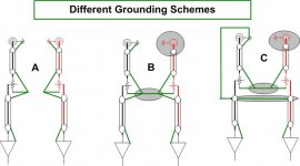
Just to make sure I understand. All of these schemes have some point(s) where they connect to earth ground. Correct?troystg said:Here is a few different ground schemes to try and see which one helps the noise the most.
peter
schro20 said:
Just to make sure I understand. All of these schemes have some point(s) where they connect to earth ground. Correct?
peter
Nope.. Signal ground and Earth ground do NOT need to meet.
But if you did want to tie the two together you can use a 10Ohm resistor and tie the RCA grd to chassis.
What does the earth symbol in your drawings signify?troystg said:Nope.. Signal ground and Earth ground do NOT need to meet.
Peter
schro20 said:
Just to make sure I understand. All of these schemes have some point(s) where they connect to earth ground. Correct?
peter
http://www.diyaudio.com/forums/showthread.php?postid=1690677#post1690677
- Home
- Amplifiers
- Chip Amps
- The new "My Ref" Rev C thread