Hope you can see the traces on the pdf.I think you have to turn off some layers to see the others?
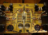
The silk screen looks fine at a glance, but the traces are of interest of course.
Where do you connect the chokes in the second stage? I noticed you added some 1R resistors in the plates of both stages, these aren't strictly necessary, but not a bad idea on the second stage. Not required for determining the plate current, although they do make that easier. Note that each channel should probably have a decoupling capacitor on its 300V rail although this is not recommended with the Salas SSHV2. (I used them with no ill effects on an SSHV2 in one of my dacs.) I would have some concern about stability without them as these tubes can oscillate in the VHF region. (0.22uF low inductance film type)
The 1R resistor is just to make some easy TP's for plate current.
The choke will be connected using two pads placed in between the Mu follower tubes.
I tried to make all the connections as short as possible.
I am planning to have the SSHV's on each side of the PCb, therefore very short connections. I will need decoupling before the SSHV definitely.
I am not sure if layout of the ground it is ok and where to connect the PSU ground ( near input, output or center(more like a star))?
Also, as I said before, I would like to have at least 15mm of the tubes exposed ( so they can be replaced when needed and for the look I guess). Not sure that this layout will not be prone to noise ( tubes are not completely screened).
-I am waiting for the chokes to be shipped in couple weeks ( don't have the dimensions yet).
In order to have the chokes as close to the connection pads as possible, I thought of using stands-offs attached to the PCB. I will try to place the choke under the tubes and in between C4(1uF) and 12V battery. How close this choke can be to C4 in your opinion? C4 is about 0.75" tall and if another 0.75" between the choke and C4 is enough, then stands-offs could be 1.5". Therefore the choke connection will be about 2-2.5" long.
In order to have the chokes as close to the connection pads as possible, I thought of using stands-offs attached to the PCB. I will try to place the choke under the tubes and in between C4(1uF) and 12V battery. How close this choke can be to C4 in your opinion? C4 is about 0.75" tall and if another 0.75" between the choke and C4 is enough, then stands-offs could be 1.5". Therefore the choke connection will be about 2-2.5" long.
Kevin,
I know you built it with separate enclosure for PSU, and I strongly believe that for low signal preamp it is better to have PSU 3 feet away.
However, it is tempting to built in single enclosure for convenience.
What is your opinion in having a split enclosure and using R-core psu transformer?
I know you built it with separate enclosure for PSU, and I strongly believe that for low signal preamp it is better to have PSU 3 feet away.
However, it is tempting to built in single enclosure for convenience.
What is your opinion in having a split enclosure and using R-core psu transformer?
A couple of concerns:
The key is to make sure you do not have external currents flowing across the ground plane, so I/O grounds should all go to a single place on the board.
All of my phono stages, the line stage and driver tubes in my system are electrostatically shielded. Power magnetics are remote to the units they are powering along with the rest of the PSU circuitry. In the case of the SSHV2 locating them with the pre-amp makes sense, but locate the rectifiers, raw filter caps and transformers in another box, and send only fairly clean DC to the pre-amp.
- The biggest being a ground loop with the supply. I assume separate windings and rectifiers and no common ground connections prior to the board ground.
- Input RCA jack grounds should be tied together at the jacks and a single line brought to the ground on the board.
- Do step 2 for the outputs as well. Ground to same place..
The key is to make sure you do not have external currents flowing across the ground plane, so I/O grounds should all go to a single place on the board.
All of my phono stages, the line stage and driver tubes in my system are electrostatically shielded. Power magnetics are remote to the units they are powering along with the rest of the PSU circuitry. In the case of the SSHV2 locating them with the pre-amp makes sense, but locate the rectifiers, raw filter caps and transformers in another box, and send only fairly clean DC to the pre-amp.
Thank you Kevin for all the "ground" help.A couple of concerns:
Expect to do some etch cutting and re-arranging if you have hum issues.
- The biggest being a ground loop with the supply. I assume separate windings and rectifiers and no common ground connections prior to the board ground.
- Input RCA jack grounds should be tied together at the jacks and a single line brought to the ground on the board.
- Do step 2 for the outputs as well. Ground to same place..
The key is to make sure you do not have external currents flowing across the ground plane, so I/O grounds should all go to a single place on the board.
All of my phono stages, the line stage and driver tubes in my system are electrostatically shielded. Power magnetics are remote to the units they are powering along with the rest of the PSU circuitry. In the case of the SSHV2 locating them with the pre-amp makes sense, but locate the rectifiers, raw filter caps and transformers in another box, and send only fairly clean DC to the pre-amp.
Yes, I am planning to have separate transformer and rectifiers, CLC for each channel.
I will change the ground plane to a star to be on the safe side.
 If I go for completely separate raw power supply( separate transformers, rectifiers, clc) that will feed SSHV on each channel, then wouldn't be better to have separate PCB's?
 In this case, when each channel has its own ground, how do I connect the grounds so I don't make a loop:
-only at the input or output
- between the boards
I know you don't have all the answers, But I am trying to think out loud... And see if it makes sense to build it on PCB or P2P.
Sorry that at this moment there are so many ifs....
I prefer P2P for most of my projects and built mine in two separate chassis, the grounds are common only in the supply..
No hum or noise either.
Mine is all ground buss, with one connection to the chassis in each box. The RCA jacks both ground at this point and the supply connects to this ground point as well.
The power supply ground point is connected to the safety ground through a 10 ohm resistor with anti-parallel diodes connected across it.
I prefer P2P for most of my projects and built mine in two separate chassis, the grounds are common only in the supply..
No hum or noise either.
Mine is all ground buss, with one connection to the chassis in each box. The RCA jacks both ground at this point and the supply connects to this ground point as well.
The power supply ground point is connected to the safety ground through a 10 ohm resistor with anti-parallel diodes connected across it.
I prefer 2p2 for tubes too. This is the first time I thought of using PCB for tube. I was trying to make things easier to assemble.
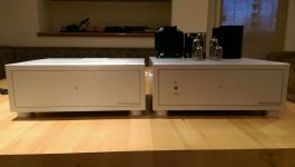
In my power amp builds I am connecting the ground bus to the safety gnd directly and never had a problem. ( see picture, PSU is in a separate enclosure). What is the role of the 10R and diode anti-parallel? Is this typical for low level signal . ( I saw this setup in the Salas's simplistic RIAA).
Attachments
What is the disadvantage for this phono stage to use single HT winding, single regulator cap input, but separate LC to each SSHV? Or even same CLC and then split to each channel SSHV? Is the difference between the above and a total separate PSU for each channel noticeable?
Hi Kevin,
Have a dilemma. I am using the RIAA EQ calculator (free from glass-ware.com) to see if I can adjust the values to what caps I have. I bought the caps from Michael Percy audio and received a C3 of 22.7nF and a C2+C7 of 8020pF (6500(bought as 0.0062uF)+1520).
I am not sure how critical the values are and have no previous experience with RIAA. I assume that is easier to change resistors values as they come with more options compare to polystyrene caps. Are you using the same calculator and if yes what values you consider for Rl (load) and Rs (source)?
Thank you for helping me figure out this phono stage.
Best regards,
Radu
The ratio of the caps is actually pretty important and you can't just trim the resistors to compensate. I recommend you trim the caps instead.  If you use the specified cap values unmeasured with a typical 5% tolerance RIAA deviation should not be worse than 0.5dB..
Based on the values you cite (6500pF) I would recommend 1000pF and 100pF as you want close to 7600pF total. eBay is actually a good source for polystyrene and Russian Teflons.
The source impedance of the first stage is will vary slightly depending on tube condition, but should generally be in the range of 9K.
If you use a single HV secondary make sure that you run only one ground return line and you probably should not use remote sensing.
The 10 ohm resistor and anti-parallel diodes keep ground loop currents at bay, preventing current flow through the safety grounds between components.
If you use the specified cap values unmeasured with a typical 5% tolerance RIAA deviation should not be worse than 0.5dB.. Based on the values you cite (6500pF) I would recommend 1000pF and 100pF as you want close to 7600pF total. eBay is actually a good source for polystyrene and Russian Teflons.
The source impedance of the first stage is will vary slightly depending on tube condition, but should generally be in the range of 9K.
If you use a single HV secondary make sure that you run only one ground return line and you probably should not use remote sensing.
The 10 ohm resistor and anti-parallel diodes keep ground loop currents at bay, preventing current flow through the safety grounds between components.
New Muscovite Build
I have been working on a Muscovite build after hearing Kevin's a lot for quite some time. Thanks to Kevin's guidance and Raymond Koomce of Time Bandit close by to me in Tyler, Texas, it is finally finished. I will set it up soon but I am so excited with the great esthetics of the unit that I wanted to post some pictures of the unit. The pictures do not do it justice, as the cases are very nice and hefty. I am very appreciative of the assistance of Raymond Koonce and Kevin to help get to done! Listening impressions later.
I have been working on a Muscovite build after hearing Kevin's a lot for quite some time. Thanks to Kevin's guidance and Raymond Koomce of Time Bandit close by to me in Tyler, Texas, it is finally finished. I will set it up soon but I am so excited with the great esthetics of the unit that I wanted to post some pictures of the unit. The pictures do not do it justice, as the cases are very nice and hefty. I am very appreciative of the assistance of Raymond Koonce and Kevin to help get to done! Listening impressions later.
Attachments
Hi Kevin -- Thanks for all the information by PM. Of all the Muscovite variations, I'm leaning towards the Muscovite with the Muscovite Mini III a close second. There are comments on the sonics of the Muscovite in this thread but nothing about the Mini III.
Could you or other builders comment on the sonic differences between these two preamps? Not sure what cartridge I'll be using. I've got an old Grado Reference Platinum in that system now but might go to a Benz or Ortofon later. Tube amp (Dyna Mk III variation) and Klipsch Forte's.
Cheers all - and thanks.
Phil
Hi Phil,
The Muscovite is the better performing of the two designs, depends on goals and budget as to what is the better choice.
The Muscovite has more gain, is somewhat quieter, and is a bit more detailed sounding overall. It is the more complex design to build and debug.
The Mini III is a bit warmer sounding, has about 5dB less gain, and is significantly less complex.
Both are well suited to use with SUTs and LOMCs, but the low input capacitance (if carefully built) would also suit MM types that are sensitive to capacitive loading.
- Home
- Source & Line
- Analogue Source
- The "Muscovite" 6S3P Tube Phonostage