Re: Hum
The resistor thing we were referring to wasn't a break resistor. We were talking about what to do with the unused signal sources on the outside of an input selector switch.
I've never had a hum problem either. They usually come from ground loops. My amps are relatively light aluminum and I assure you, it doesn't cause a problem.
I'm tempted to add weight inside the amp, but only to help keep it in place so the weight of all the xlr plugs and speaker wires don't tip it over like they do now.
-Nick
mhouston said:I have seen a few variations on the100ohm ground resistor. One is the 10ohm ground resistor and another is either of these with a very small cap across it e.g. .033uf You may have to experiment if you have this problem I’ve never had enough hum (in my resonance controlled amps) to have to worry about it.
The resistor thing we were referring to wasn't a break resistor. We were talking about what to do with the unused signal sources on the outside of an input selector switch.
I've never had a hum problem either. They usually come from ground loops. My amps are relatively light aluminum and I assure you, it doesn't cause a problem.
I'm tempted to add weight inside the amp, but only to help keep it in place so the weight of all the xlr plugs and speaker wires don't tip it over like they do now.
-Nick
Chip amp sound
Some-one said they were going back to transistors because chip amps sound like chip amps. Who was that and what did you mean? I like my chip amp monoblocks. But I'm open to an expalination.
I'm not having a go at anyone. I have valve, MOSFet, transistor and chip amps and I like them all for different reasons.
You got that right!I don't get the impression that uncle_leon is confused, except maybe by all this crazy talk of grounding sources.
")
I mean, when giving me clues don't assume that anything will be "obvious" to me. But I can assure you, it will only take one explanation for me to grab the idea - if it has some reasonable basis, that is
That's very reasonable point. There's no use going to esoteric heights with one component, while terribly lacking in some other area. Balance is the key - that's why I'm looking for some new CD player alreadyI don't think there's a lot of "effective" upgrades to do, aside from things like biamping, maybe working on the power supply, etc. Real changes, not the same circuit with expensive parts..
I still stand by the suggestion that you should do what you want to make it look nice on your shelf, make it work properly for the purpose, and consider it done. Instead of tweaking for things you can't even hear, look at your speakers/crossovers, or try an active biamp or something. Something you can really improve upon.
Peter, everything seems to work well in your amplifiers, even if it shouldn't, according to the laws of physicsYou don't really need DC blocking caps for two amps in parallel. I was supplying GC modules for those speakers (passive bi-amping): http://soundfusion.ca/Ariel.htm and everything worked fine without those caps.
So I will just trust you on this one.BTW, one of my friends offered that he'll refund me the cost of bigger power caps, if they happen to sound worse. He said that with such low capacitance I should be easily able to hear mains noise. Well, that was quite true when I forgot to shut down the amp before disconnecting the source from input - it sounded very much like 50Hz (and scared the hell out of me by the way).
uncle_leon said:BTW, one of my friends offered that he'll refund me the cost of bigger power caps, if they happen to sound worse. He said that with such low capacitance I should be easily able to hear mains noise. Well, that was quite true when I forgot to shut down the amp before disconnecting the source from input - it sounded very much like 50Hz (and scared the hell out of me by the way).
You'll still get that WAHHH noise in those circumstances regardless of PSU caps.
I'd probably consider taking him up on the offer. You can get a 4700 or 6800 uF cap for $3-$4 Canadian, even if you put a pair per channel, you're still talking under $20.
I can't imagine it sounding worse (though some will disagree).
I also doubt it will sound much better, since I never noticed a problem with my old one at 1500uF per channel, you'll definitely reduce ripple voltage though, and maybe raise your threshold of clipping slightly.
For the small amount it will cost you though, you're more likely to see improvement than anywhere else.
The DC cap(s) might not be a bad plan anyways. If you pick ones in a reasonable size I doubt you could hear any difference, and if you ever plug in a defective source, or have one of your components fry, it won't throw your woofer cone out on the floor. (tweeters usually stay put, but smell bad and stop working afterwards)
-Nick
Samml power caps
What about the theory that small power caps, especially low ESR caps, give better midrange. Conversely large power caps-better bass?
I only use 2000uf caps on my LM3875 chip amps (at the chip itself) and 4.7 polies at the rectifier and my mid range and sound stage is staggering (I think so anyhow).
What about the theory that small power caps, especially low ESR caps, give better midrange. Conversely large power caps-better bass?
I only use 2000uf caps on my LM3875 chip amps (at the chip itself) and 4.7 polies at the rectifier and my mid range and sound stage is staggering (I think so anyhow).
If you are going to use dc blocking caps, can I recomend a cap. Sonicaps, bypassed by 15pf Vishay 1837 is a very nice sounding combination. I use this further up my signal path (where it was unavoidable) and found it a very nice improvement on stacked film polys.
They need about 50 hours to break in, though they start sounding very good, degrade then improve again.
I haven't tried the BG's to pass comment on differences.
The Sonis are reasonably priced compared to other "boutique" components.
Like Peter, I have no DC blocking before the amp, and have no adverse effects that I have been able to measure DC wise. (I am a noob, so slightly nervy that I may be measuring wrong). My tweets though use a cap as a filter (replaced with a sonicap to good effect) so I dont worry about damage
Re: Samml power caps
I never noticed a difference when I built my new supply with 68000uF per rail. (I have a half dozen of these big caps sitting around, so I figured I may as well use some)
I think the theory is based on someone's flawed logic. I mean, big caps must be slower than small ones.... Right?
Truly, they're in the power supply, what harm could they do? The only thing I can think of that IS worse about big caps is higher ripple current and shorter switching pulses from the diode. And I guess bad power factor, though that's more of an efficiency thing,.
What a power supply cap does is tries to keep the amplifier's input voltage constant in order to keep the input variations from getting modulated onto the output. I don't think you can do that too much.
I think the better bass thing is bunk too. Probably because most people know that bass takes more power, so if your power supply has more caps, it must be more powerful.
In truth, it's mostly the transformer. If the transformer can put the power in faster than your amplifier can take it out, your caps will be fully recharged 60 times per second. If your cap is big enough that its voltage doesn't fall below the desired output voltage (+ a bit since the amp isn't perfect) things should be okay.
This is where PSRR matters. an amp with absolutely no PSRR will be exactly modulated with the input ripple. (You'll hear the ripple exactly as is) The greater the PSRR, the smaller the amount of ripple which makes it into your output signal.
These amps have a pretty decent PSRR, so you don't need a big cap, but having less ripple means that you'll get the same percentage of a smaller amount, therefore less ripple on the output.
I don't see how a smaller cap is going to be better for anything...
-Nick
mhouston said:What about the theory that small power caps, especially low ESR caps, give better midrange. Conversely large power caps-better bass?
I only use 2000uf caps on my LM3875 chip amps (at the chip itself) and 4.7 polies at the rectifier and my mid range and sound stage is staggering (I think so anyhow).
I never noticed a difference when I built my new supply with 68000uF per rail. (I have a half dozen of these big caps sitting around, so I figured I may as well use some)
I think the theory is based on someone's flawed logic. I mean, big caps must be slower than small ones.... Right?
Truly, they're in the power supply, what harm could they do? The only thing I can think of that IS worse about big caps is higher ripple current and shorter switching pulses from the diode. And I guess bad power factor, though that's more of an efficiency thing,.
What a power supply cap does is tries to keep the amplifier's input voltage constant in order to keep the input variations from getting modulated onto the output. I don't think you can do that too much.
I think the better bass thing is bunk too. Probably because most people know that bass takes more power, so if your power supply has more caps, it must be more powerful.
In truth, it's mostly the transformer. If the transformer can put the power in faster than your amplifier can take it out, your caps will be fully recharged 60 times per second. If your cap is big enough that its voltage doesn't fall below the desired output voltage (+ a bit since the amp isn't perfect) things should be okay.
This is where PSRR matters. an amp with absolutely no PSRR will be exactly modulated with the input ripple. (You'll hear the ripple exactly as is) The greater the PSRR, the smaller the amount of ripple which makes it into your output signal.
These amps have a pretty decent PSRR, so you don't need a big cap, but having less ripple means that you'll get the same percentage of a smaller amount, therefore less ripple on the output.
I don't see how a smaller cap is going to be better for anything...
-Nick
buffers for Ghip amps
I found my chips amps (two in all - http://www.diyaudioprojects.com/Chip/Nanoo/index.htm ) sounded much better when played through one of my preamps. I use valve preamps. I think they definitely require a buffer, valve or solid state. It maybe the load they place back on the sourse or how they react to most cables. I find the valve preamp and chip amp combo the best.
I'm from the school that believes the best upgrade for a GC is a better source/buffer or preamp.... those have made the most improvement in my system based on My_ref C.
I found my chips amps (two in all - http://www.diyaudioprojects.com/Chip/Nanoo/index.htm ) sounded much better when played through one of my preamps. I use valve preamps. I think they definitely require a buffer, valve or solid state. It maybe the load they place back on the sourse or how they react to most cables. I find the valve preamp and chip amp combo the best.
Hi Leon,
I had to go back some way to find your questions.
An RCA Y connector will have three RCA plugs on it. One goes to the source and two go to the receivers (amplifiers). This allows the same signal to be sent to each amplifier. If you can't find one you can easily build one if you can solder coax into RCAs.
The stereo amp next to the speaker terminals allows one channel to drive treble and the other channel to drive bass/mid. The speaker cables can be just 1 to 2feet long. When this short, the effect (if any) of very expensive cables will be much less. There is low inductance and low capacitance due to the short lengths, and if you choose you can also have low resistance depending on the size of the copper conductor.
Keep in mind that tin (Sn) plated and tinned (Pb/Sn) and silver plated (Ag) are all different and many retailers mix them up.
The non inverting DC coupled chipamp has an input impedance of 20k set by that resistor to ground. The non-inverting input sees 200r plus 20k//Rs as its source resistance. If Rs=100r then source resistance is 299r5.
The inverting input sees the two NFB resistors in parallel. (620r//20k=601r4). The DC offset will be dependant on the difference between these to resistances and the current flowing through them.
Now to the DC blocking.
I see two big decisions
1.) use the DC block as part of the crossover for the treble amplifier or keep the DC block frequency low enough to avoid interaction with the crossover and it's slopes.
I would go for separation and set DC block a full decade below the crossover.
2.) DC block just the non-inverting input or DC block both inputs.
The schematic has a fairly close match between the source impedances. If you block only the non-inverting then you will get a much bigger source resistance difference leading to a much bigger DC output offset. If your crossover starts with a capacitor (many treble filters do exactly this) then ignore the problem. If offset could affect the downstream side then your solution is to block the lower leg of the NFB AND the input. If done this way the source resistances match again at about 20k. There will be a slightly higher drift in output offset with temperature due to the higher resistances but tolerable.
Use the standard formula for deciding the size of blocking capacitor.
eg. for a crossover at 3kHz and Zin=20k C=1/2/Pi/Zin/F (F=3kHz/10=300Hz) C=1/2/3.14/20,000/300=27nF.
The NFB should be set at least half an octave below this, so F=200Hz. C=1/2/3.14/620/200=1.3uF.
The smoothing caps for 8ohm should be 150uF and double this for 4ohm (now, we begin to see why Peter Daniel suggests 1500uF, it's all down to exemplary mid frequency reproduction into very high efficiency speakers). This combination will allow good performance from the chipamp down to 3kHz. Scale all these inversely for other crossover frequencies.
I hope this helps with your decisions.
Re: buffers for Ghip amps
That was me....
Chipamps are not bad per se, you can't buy anything in the shops under $200 that will sound better...... BUT... after some time you will realise the "sound" of the gainclone... it is like a component to the music that is always there.... listeining to a various artist CD does not have the same variety in sound stage and ambiance..... its like everything sounds just a little bit the same....
I have tried simple cathode follower buffers, but they souned too laid back, yet very smooth... but I did not like the HF rolloff...curently using a mosfet/jfet hybrid preamp.
mhouston said:Some-one said they were going back to transistors because chip amps sound like chip amps. Who was that and what did you mean? I like my chip amp monoblocks. But I'm open to an expalination.
I'm not having a go at anyone. I have valve, MOSFet, transistor and chip amps and I like them all for different reasons.
That was me....
Chipamps are not bad per se, you can't buy anything in the shops under $200 that will sound better...... BUT... after some time you will realise the "sound" of the gainclone... it is like a component to the music that is always there.... listeining to a various artist CD does not have the same variety in sound stage and ambiance..... its like everything sounds just a little bit the same....
mhouston said:
I found my chips amps (two in all - http://www.diyaudioprojects.com/Chip/Nanoo/index.htm ) sounded much better when played through one of my preamps. I use valve preamps. I think they definitely require a buffer, valve or solid state. It maybe the load they place back on the sourse or how they react to most cables. I find the valve preamp and chip amp combo the best.
I have tried simple cathode follower buffers, but they souned too laid back, yet very smooth... but I did not like the HF rolloff...curently using a mosfet/jfet hybrid preamp.
A chip off the old block
Thanks for getting back to me. I’m new at forum. I have not yet experienced what you are saying with the chips but I can well imagine that you are right. At some point I may just say “enough” and put my mono blocks in moth balls.
One of the first amps I built in this particular “second coming” (there have been a few over 40 years) was a K-12M valve amp from s5electronics. I heavily modded it of course. It got me back from the brings of Sansui Suicide. This little valve amp and a new NAD C542 and transparent cables opened me up to the emotion of the music. When I built my chip amp monoblocks I always felt something was missing. There was a lot more there (56Wpc compared to 8Wpc) but there was a lack of emotion. When I added the valve preamp up front the emotion returned and now I feel it is a killer combo.
Thanks for your comment. I’m building a 211 based amp (25Wpc) running on 1300V and a couple of 6T9s (I usually build two or three of each amp-improving it each time) so it may be chips-away. But until then I’m stuck on the valve pre-chip power combo…..
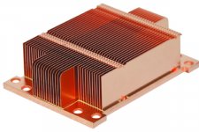
I got my new heatsinks for the amp chips (for just £5 each, brand new). If these copper babes won't keep the amp cool, I'm going to build a water cooling system (again), I'm serious.
But honestly, I don't think there will be such need - the heatsinks were designed for Xeon workstation processors, and should be able to cope with lot more heat than what LM chip can generate.
As to DC blocking, thanks for explanations, but I will first try it without them anyway. My amp is going to be a truly minimalistic design, it doesn't even have any fuses yet
Attachments
As to DC blocking, thanks for explanations, but I will first try it without them anyway.
Check the DC offset coming form the previous stage. If it is negligable then you don't need DC blocking caps!
AndrewT said:Hi Uncle,
that copper sink looks like it is intended for fan cooling.
Without a fan (even a slow turning one) it will dissipate between 10% and 30% of it's rated capacity.
depends which version of the xeon its designed for, I would guess with fan that chunk of copper can dissipate 90-110w of heat.
In its favour, its copper, has a good surface area, and a solid base. Downside is those fins are close together.
I reckon it will be more than 10% probably 20% of rated capacity used passive. That would give a minimum of 22w disipation probably more.
I would think you can get good power out a chip amp with that kind of dispertion.
As I said earlier in the thread - I may be a beginner in building audio electronics, but definitely I'm NOT one in building cooling systems But thanks for your replies anyway
I'm going to use some fan to help dissipate the heat, but it will be powered through external power supply, and shielded off from amps by radiators. I will for sure include some manual rpm control by pot, to ensure the fan runs silently. Maybe I will include some automatic (based on radiator's temperature) regulation too, as an option.
But thanks for your replies anyway I'm going to use some fan to help dissipate the heat, but it will be powered through external power supply, and shielded off from amps by radiators. I will for sure include some manual rpm control by pot, to ensure the fan runs silently. Maybe I will include some automatic (based on radiator's temperature) regulation too, as an option.
That looks like it's for a 1u server, and it probably relies on the chassis' fans to move the air.
I don't expect you'll need a whole lot of airflow. Convection might even move enough air. Gotta remember that it's not class A, so your long term average dissipation isn't going to be all that high.
If you do end up using a fan are you planning on reducing the fan current with a regulator, or just directly dropping it with a pot?
-Nick
I know it would do fine without any fans (especially that the chassis will be a kind of open-style design). I'm going to mount one only as "the icing on the cake", if you know what I mean
I think I will include a switch between manual (pot) and automatic (regulator+thermal diode) regulation mode. Or I will make it a hybrid solution - auto control, but with pot on regulator's voltage input, so that I can easily match it with any fan type / PSU voltage. Of course, I'm going to set it so that at 'normal' temperatures the fan will be barely spinning. Yeah, I think, that's the way to go. Plus on/off switch, perhaps. And a fuse, maybe, in case the fan motor fails and shorts regulator's outputs.
I think I will include a switch between manual (pot) and automatic (regulator+thermal diode) regulation mode. Or I will make it a hybrid solution - auto control, but with pot on regulator's voltage input, so that I can easily match it with any fan type / PSU voltage. Of course, I'm going to set it so that at 'normal' temperatures the fan will be barely spinning. Yeah, I think, that's the way to go. Plus on/off switch, perhaps. And a fuse, maybe, in case the fan motor fails and shorts regulator's outputs.
- Status
- This old topic is closed. If you want to reopen this topic, contact a moderator using the "Report Post" button.
- Home
- Amplifiers
- Chip Amps
- The most effective Gainclone upgrades