AndrewT said:
Plastic will have no effect on magnetic or electric fields.
If there's a mechanical vibration which can be damped by the plastic, there is _some_ electrical/magnetic effect, though it will be completely negligible.
potted are less likely to hum, that's their main advantage. Because of that, there's probably a bit less chance of failure due to wear between the windings. Again, probably pretty negligible unless you're really abusing it.
-Nick
Sharpi31, why did you put copper foil on the chip? Is you transformer very close to it, or for some other reason?
And did it make any actually audible difference?
Next thing, did you find 220R resistor on input necessary? Peter Daniel suggests to ommit it, because in most cases everything works fine without it.
And the third question, what is the schamatic for this amp?
Oh, and where is feedback loop resistor? Is it behind the chip?
I managed to find a batch of 100 on ebay a while back. I could spare 8 if you need some... the caps cost very little but postage to Hawaii might be a bit costly! email me at james.r.sharp@gmail.com if you're keen ") I'm not going to use all 100!
I'm not going to use all 100!
I'm not going to use all 100!uncle_leon,
I haven't tried omitting the 220R - should be easy to short out though... I'll try this and see.
I shielded the chip because I found a massive difference doing this with the tripath chips. I'm sure it helps lose the heat from the chip too. I have a 50m roll of induction loop copper tape, so couldn't resist.
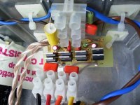
Panomaniac (I think) reported that the welwyn rc55 was a good choice for feedback, and I had some of these to hand. I have used kiwame everywhere else, but this would be too large to achieve a very short feedback loop. The welwyn is soldered on the back of the chip where the pins appear from the chip body - with this chip, you could not get a shorter feedback loop than using this technique. The profile of the welwyn is so low that even with a heatsink cover, the resistor doesn't prevent the chip lying flat on the heatsink enclosure.
My last gainclone used BG standard at the rectifier and BG N on the chip. This new sikorel amp is substantially better, but since i changed many other components i can't attribute the improvement solely to the upgrade in caps.
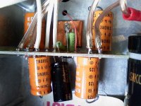
This amp uses Peter Daniel's excellent gold PCB. I have BG N 4.7uF at the rectifier, and 10000uF sikorels on each power rail. I calculated a snubber value of 39ohm in series with 0.1uF for damping at 250KHz (where the LM3875 is quite sensitive to noise, apparently) and mounted this on the rectifier board too. The caps on the amp board are 2x 470uF sikorel per rail per channel, with the BG standard 47uF sitiing accross V+ and V-.
I tried small bypasses at the chip pins and this muddied the sound considerably. The 47uF BG seems to focus the sound significantly and lowers the subjective noise floor.
I have liked the Kiwames from the first time i tried them - very smooth and spacious. The dynamics of the sikorels work well in combination.
I haven't tried omitting the 220R - should be easy to short out though... I'll try this and see.
I shielded the chip because I found a massive difference doing this with the tripath chips. I'm sure it helps lose the heat from the chip too. I have a 50m roll of induction loop copper tape, so couldn't resist.
Panomaniac (I think) reported that the welwyn rc55 was a good choice for feedback, and I had some of these to hand. I have used kiwame everywhere else, but this would be too large to achieve a very short feedback loop. The welwyn is soldered on the back of the chip where the pins appear from the chip body - with this chip, you could not get a shorter feedback loop than using this technique. The profile of the welwyn is so low that even with a heatsink cover, the resistor doesn't prevent the chip lying flat on the heatsink enclosure.
My last gainclone used BG standard at the rectifier and BG N on the chip. This new sikorel amp is substantially better, but since i changed many other components i can't attribute the improvement solely to the upgrade in caps.
This amp uses Peter Daniel's excellent gold PCB. I have BG N 4.7uF at the rectifier, and 10000uF sikorels on each power rail. I calculated a snubber value of 39ohm in series with 0.1uF for damping at 250KHz (where the LM3875 is quite sensitive to noise, apparently) and mounted this on the rectifier board too. The caps on the amp board are 2x 470uF sikorel per rail per channel, with the BG standard 47uF sitiing accross V+ and V-.
I tried small bypasses at the chip pins and this muddied the sound considerably. The 47uF BG seems to focus the sound significantly and lowers the subjective noise floor.
I have liked the Kiwames from the first time i tried them - very smooth and spacious. The dynamics of the sikorels work well in combination.
The design looks very promising. Although right now, I'm quite convinced that the power of GCs lies mainly in their simplicity, so I'd try to get rid of some parts from it
Can you further explain what do you mean by "lowers the subjective noise floor"? Shouldn't the amp be dead silent anyway (I mean, when you mute the source)?
Can you further explain what do you mean by "lowers the subjective noise floor"? Shouldn't the amp be dead silent anyway (I mean, when you mute the source)?
sharpi31 said:I tried small bypasses at the chip pins and this muddied the sound considerably.
I couldn't tell the difference with or without 0.1uF ceramic bypass caps across each rail (0805 X7R ceramic caps literally right at the pins) of my LM3875 based amps. The sound is far from muddled too!
a very nice site about power supplies. it is for DC heaters in tubes but a power supply is a supply no matter where it is used.
the power supply in the article is very similar to those used in chipamps.
http://www.clarisonus.com/Research Reports/RR002-DCFilterTest/RR002-DCFilSupplyTest.html
the power supply in the article is very similar to those used in chipamps.
http://www.clarisonus.com/Research Reports/RR002-DCFilterTest/RR002-DCFilSupplyTest.html
by 'lowered the subjective noise floor' i meant that notes seem to decay longer and the background seems darker. Similar to a high contrast display with greater blacks, if you know what I mean.
I tried just the 940uF per rail per chip and this sounded forward to me, and mains hum could be heard from a couple of feet in front of the speakers (i have a range of high to very high sensitivity speakers). I then added 2200uF per rail which solidified the sound but the mains hum was still slightly audible. Moving up to 10000uF removed all remaining hum, and I can't hear anything even with my ear to the speaker.
I went through all this before with 1000uF pana FMs on the chip - adding a big reservoir cap killed the life of the music, and the usual 1ohm 0.1uF snubber added kick and sparkle but wasn't neutral to me.
These big sikorels (with the 39ohm 0.1uF snubber) are a completely different story ;-) None of the life of the lo-cap psu is lost (to my ears with my speakers) but this amp has balls.
This is the rectifier. You can see the mains filtering at the top and bypasses on the secondaries too.
My experience of these amps is fair but not up to the level of others in this forum. I'm keen to bring this to the UK DiyAudio meet to see how it compares to other amps... I'm really keen to hear other peoples efforts as this is the only way to learn.
My experience of these amps is fair but not up to the level of others in this forum. I'm keen to bring this to the UK DiyAudio meet to see how it compares to other amps... I'm really keen to hear other peoples efforts as this is the only way to learn.
Attachments
Peter Daniel said:
The biggest change, in my system, came with using small BG N caps directly at the chip
.
Hi Peter. Can you tell me what value did you use and what pins in the chip did you connect them to?
Thank you very much
Peter Daniel said:
That's right on, a simple GC is still the best GC and I was promoting it for last three years without basically changing anything in my initial circuit.
Regulated supplies, batteries, switching supplies, snubbers, Zobels, big caps, all came and are gone now (at least for me), and simple GC still rules.;-)
Panasonic FC caps are indeed the best value for the money and it's hard to improve on them.
The biggest change, in my system, came with using small BG N caps directly at the chip and larger BG STD at the rectifiers. That changed the sound in a right direction and for me there was no way back. Although some of my friends still prefer large BG STD at the amp.
Attached is schemnatic of my Patek amp.
that's good
Sharpi31,
looking at the pictures you provided, it seems that the snubber that you used to such good effect is different from those used by Peter, and not only because it uses different value. Yours seems to be a .1uf cap, a 39ohm resistor, a 4.7 cap. Peter removes the 4.7 cap and connects the resistor directly to the + or - voltages. Thus, your resistor is sandwiched by two caps. Did I understand your implementation correctly? Thanks.
looking at the pictures you provided, it seems that the snubber that you used to such good effect is different from those used by Peter, and not only because it uses different value. Yours seems to be a .1uf cap, a 39ohm resistor, a 4.7 cap. Peter removes the 4.7 cap and connects the resistor directly to the + or - voltages. Thus, your resistor is sandwiched by two caps. Did I understand your implementation correctly? Thanks.
- Status
- This old topic is closed. If you want to reopen this topic, contact a moderator using the "Report Post" button.
- Home
- Amplifiers
- Chip Amps
- The most effective Gainclone upgrades