Hi,
There's no need to anyway. I very much doubt you'd hear the difference at such low impedances.
Go for eloctrolytic caps and bypass with decent polyprop ones.
Cheers,")
BTW, if it where me I'd lose the cathode resistors bypasses or at the very least have a listen without those. Plus, that WCF stage can be improved too and don't forget the importance of the PSU.
Cheers,
There's no need to anyway. I very much doubt you'd hear the difference at such low impedances.
Go for eloctrolytic caps and bypass with decent polyprop ones.
Cheers,
BTW, if it where me I'd lose the cathode resistors bypasses or at the very least have a listen without those. Plus, that WCF stage can be improved too and don't forget the importance of the PSU.
Cheers,
Go for eloctrolytic caps and bypass with decent polyprop ones
I would head what Frank says. I have been breadboarding various headphone topologies lately and was thinking the same thing, I don't want any lytics' in the signal path. I was using a 2uF electrolytic and swapped it with a polypropylene and I can't hear the difference FWIW.
I am building the otimized.
For C1 I plan on using UFG1A102MHM1TO Nichicon | Mouser
For C2 715P47454MD3 Vishay / Sprague | Mouser
C3 UFG1A222MHM Nichicon | Mouser
C4 LGU2G471MELC Nichicon | Mouser
Transformer 269AX Hammond Manufacturing | Mouser
An externally hosted image should be here but it was not working when we last tested it.
For C1 I plan on using UFG1A102MHM1TO Nichicon | Mouser
For C2 715P47454MD3 Vishay / Sprague | Mouser
C3 UFG1A222MHM Nichicon | Mouser
C4 LGU2G471MELC Nichicon | Mouser
Transformer 269AX Hammond Manufacturing | Mouser
Hi,
There's no need to anyway. I very much doubt you'd hear the difference at such low impedances.
Go for eloctrolytic caps and bypass with decent polyprop ones.
Cheers,
BTW, if it where me I'd lose the cathode resistors bypasses or at the very least have a listen without those. Plus, that WCF stage can be improved too and don't forget the importance of the PSU.
Cheers,
Why would you bypass the cathode tube resistors? I assumed they are to step the current down before it runs to ground.
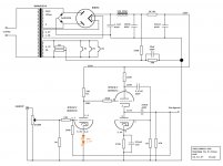
Here is the power circuit I plan on using.
I assume the capacitors are not a big deal on the power side. I had toyed with the idea of using tubes to rectify but I keep reading that diodes are better.
An externally hosted image should be here but it was not working when we last tested it.
I assume the capacitors are not a big deal on the power side. I had toyed with the idea of using tubes to rectify but I keep reading that diodes are better.
Hi,
Well, I said I would not bypass the cathode resistors. For several reasons actually but mostly because they don't make the circuit sound as good as it could.
Then again a circuit diagram is just that, without PS it's just meaningless to me. Just as it is obviously meaningless to you.
Cheers,
Why would you bypass the cathode tube resistors? I assumed they are to step the current down before it runs to ground.
Well, I said I would not bypass the cathode resistors. For several reasons actually but mostly because they don't make the circuit sound as good as it could.
Then again a circuit diagram is just that, without PS it's just meaningless to me. Just as it is obviously meaningless to you.
Cheers,
This is how I built mine 7 years ago... pic of the amp was in the other thread.
LED bias was suggested and tutored by Morgan Jones himself in email exchange
Did you experiment alot with the global feedback?
No I didn't.Did you experiment alot with the global feedback?
It was Morgan's recommendation to use feedback to tighten up the sound some... and it did.
But the amplifier never really convinced me so I eventually sold it.
Hi,
PS = Power Supply.
Cheers,
That is what I assumed.
I would like to go ahead and apologize in advance for not understanding tube audio circuit and power supply design in a few days of reading. It is a lot to absorb.
No I didn't.
It was Morgan's recommendation to use feedback to tighten up the sound some... and it did.
But the amplifier never really convinced me so I eventually sold it.
What didn't you like about the amp?
Hi,
One of the problems using a WCF as an output buffer is that it is sensitive to the external load. No big deal with high impedance headphones but not ideal using really low impedance ones.
Another problem is that PSRR isn't very good so it would require a well designed PS.
For those using high impedance headphones, I'd recommend losing the cathode bypass caps and use the same value cathode resistor of the WCF and insert it between cathode and anode of the two triode halves, then take the signal off the anode of the bottom triode. It's the same topology as I've used in most of the buffers I designed and works very well.
Cheers,
Hi,
One of the problems using a WCF as an output buffer is that it is sensitive to the external load. No big deal with high impedance headphones but not ideal using really low impedance ones.
Another problem is that PSRR isn't very good so it would require a well designed PS.
For those using high impedance headphones, I'd recommend losing the cathode bypass caps and use the same value cathode resistor of the WCF and insert it between cathode and anode of the two triode halves, then take the signal off the anode of the bottom triode. It's the same topology as I've used in most of the buffers I designed and works very well.
Cheers,
Looks like yours and stixx's recommendations are the same or at least very similar.
I plan on getting the diodes and the capacitor/resistor and seeing how different they sound.
From what I gathered the capacitor and resistor are suppose to make up for poor power supply design, the bypass increases grain which can add more distortion.
I like the idea of using a tube to rectify but I think I will be pushing the transformer I selected and I don't know how to redesign the ps.
The cathode resistor is there to create a bias between grid and cathode. The side effect is that it creates a modulation in AC voltage on the cathode that is in phase with the grid modulation. This acts as negative feedback and the amplification gets lower. We can annulate this with a capacitor large enough to bypass the audio signal AC to ground. Then the cathode is not mudulated anymore. If the cap is not fault free to do this, as it never is, it also creates a portion of distortion.
Last edited:
What didn't you like about the amp?
I used it on high impedance Sennheiser cans only, and the amplifier was dead silent. But it always sounded a bit lifeless and veiled (in comparison to other amps that I have built). I attributed that to the big electrolytic output caps and have since turned to output transformers (parafeed or single ended).
- Home
- Amplifiers
- Tubes / Valves
- The Morgan Jones mini tube headphone Amplifier