Both those are a sight to see , Alex. I will admit , as I follow Cordell - technically , your layout skills are to be saluted.  Really !
My only "issue" is fatter pads. The reason is - not all will go to the board house and may decide to break out the etchant and go to it ourselves. Some board house FR-4 is also more prone to pad separation ,as well.
To comment on the "long board" - you did not use the to-92's on the VAS. This will also work thermally and electrically. BD135/136 low Vceo pair is actually preferred to the KSA/C. Same for the diamond pair in the OP , they also only see a couple Volts C-E , one of the advantages Cordell points out in "the book" .I am confused by exactly what circuit you used on the long board , it looks like a "different triple". keep in mind that Cordell's DBT needs the driver /pre separate and in thermal contact to accomplish the Vbe cancellation.
Go with my above LX to the letter (couple pre/driver - separate PCB HS) and it will excel in real life.
PS - on "my board" the center Vbe is a cable that goes to the MAIN heatsink , not to the "DBT" PCB driver heatsink (notice the different pads).
OS
Really !My only "issue" is fatter pads. The reason is - not all will go to the board house and may decide to break out the etchant and go to it ourselves. Some board house FR-4 is also more prone to pad separation ,as well.
To comment on the "long board" - you did not use the to-92's on the VAS. This will also work thermally and electrically. BD135/136 low Vceo pair is actually preferred to the KSA/C. Same for the diamond pair in the OP , they also only see a couple Volts C-E , one of the advantages Cordell points out in "the book"
.I am confused by exactly what circuit you used on the long board , it looks like a "different triple". keep in mind that Cordell's DBT needs the driver /pre separate and in thermal contact to accomplish the Vbe cancellation.Go with my above LX to the letter (couple pre/driver - separate PCB HS) and it will excel in real life.
PS - on "my board" the center Vbe is a cable that goes to the MAIN heatsink , not to the "DBT" PCB driver heatsink (notice the different pads).
OS
Last edited:

For Alex MM ...
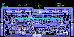
Look at (below 1) , I think it is self- explanatory. (below 2) are the actual TO-3p's over the printed output. The aluminum L will be 35 - 45mm , 25mm of the board goes under the aluminum , devices mount on top. TO-247's might need the OP device mounting holes further away from the line by 3mm.
This board would go on this - Conrad Heatsinks - Products
MF-20 /30 or similar.
For the "long board" , it's only purpose is for a massive power stage (6 pair OP - 300/8R - 500/4R).
Those who would go for a 300W/500w amp would have a 125 X 300mm conrad heatsink Conrad Heatsinks - Products
or similar.
PCB can be 275 X 75 or 100mm in this case. Being flat mounted , with a 100mm high unit, the Op devices would have to be FULLY under the PCB. Your layout would still work with the 150mm heatsink height.
Just keep in mind to leave room for a decent extruded heatsink for the - PCB mounted/separate - driver/ predriver thermal setup. Something like a 85 X 50 X 12mm extruded heatsink
http://www.mmmetals.com/extrusions/drawings/MM34400.JPG.
These are the real world , available , most adequate (C/W wise) solutions for these amps. To offer both PCB's would allow for any case/layout to be used.
OS
Attachments
Last edited:
I have gone back to using my BX boards as I am having trouble getting the AX ones going.
I think I damaged some transistors (I put Q4 upside down). The AX powered up after I corrected my mistake, but then after about 5 minutes of lowish listening, the output drivers blew on one channel. and the other channel had a strange distortion at mid frequencies. I have all the small transistors here but am having trouble getting the 2SC3503/2SA1381 transistors in Aus without paying silly postage fees from the US. The ones I were using were from eBay (2SA1360 & 2SC3423) so I'm not sure of there quality.
Anyway, I was just going over all the boards and realised that I have Panasonic FC caps throughout for all the electro's. Is this ok or should any of them not be low esr?
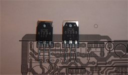
These are my present ones (ax).
(below 1) They are 2 months old now in my home theater (using them now). Are you using those ? I think even the last ones (ax's) with the cascodes were working for 3-4 months before I sold them. The caps are fantastic , but the EBAY semi's , who knows. Show some pictures so I know what boards you have .
PS , use mje340/350 if you can't source 1381/3503's ... just a slight performance downgrade , not much at all ... in fact. 2sa/c 970/2240 can be subbed for the 1845/992's, as well .
OS
Attachments
Last edited:
Thanks OS,
I'm not using those Ax boards, in fact I don't think you released that one for us.
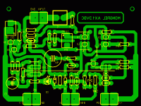
I have built the AX boards according to your PCB files and BOM on your Mongrel website.
My camera is on charge, will post pics later.
PS. I just found the other thread on your new DIYA amp. Very tempted.
I'm not using those Ax boards, in fact I don't think you released that one for us.
I have built the AX boards according to your PCB files and BOM on your Mongrel website.
My camera is on charge, will post pics later.
PS. I just found the other thread on your new DIYA amp. Very tempted.
Yep , you have the "ax vb" That one is in my barn , 4 months at least. 3 pair more are in the "field". It had the bridged trace  , the cascode, and had just a tad more turn-on "thump" than the slightly updated one. BUT , it works flawlessly. The new one is just your's edited for a cascode-less version.
In that one I used the SS9014 input pair (EBC) , quietest amp I ever produced.
So , There must be some issue with some device (or devices). The new one (DIYA amp) is derived from the VB with the better "thump-free" CCS's. The CCS's also have basestoppers to keep them even more stable. I doubt whether your amp oscillated , if it did before the drivers went up in smoke the 10R Zobel would of burned first.
The only flaw was the one you pointed out (the bridged trace). Besides that , both AX modules are just about as tough as they get. I never blew one yet out of 20+ modules.
OS
OS
, the cascode, and had just a tad more turn-on "thump" than the slightly updated one. BUT , it works flawlessly. The new one is just your's edited for a cascode-less version.In that one I used the SS9014 input pair (EBC) , quietest amp I ever produced.
So , There must be some issue with some device (or devices). The new one (DIYA amp) is derived from the VB with the better "thump-free" CCS's. The CCS's also have basestoppers to keep them even more stable. I doubt whether your amp oscillated , if it did before the drivers went up in smoke the 10R Zobel would of burned first.
The only flaw was the one you pointed out (the bridged trace). Besides that , both AX modules are just about as tough as they get. I never blew one yet out of 20+ modules.
OS
OS
Last edited:
Hi,
I am new to this thread and almost new to the forum. This winter, I decided to build myself a good power amplifer and after quite a lot of browsing for different designs I started to build a AX1.3VB +PB250. The whole process is rather slow due to many other things that needs to be taken care of (family, house, work ....). The PCBs were ready in february and I actually started to build in may. I modifed the AX design to the version without the cascode that appeared later in this thread.
Anyway some weeks ago I was ready to start testing. I experienced something similar as Repeet with distortions at some frequencies. On one of the two set of boards it was more pronounced and from the oscilloscope it seems that there is some oscillation at a higher frequencies making the response at audio frequencies look distorted. I tried many things to avoid this, but the only thing that worked was to remove the TMC network, as described in OSs schematics,. Then it became rock stable. However I still have a lot more testing to do before I am completely done. I have so far only tested into a 4 Ohm resistive load yet. Has anyone else experienced something similar? How large is the difference in sound quality with/without the TMC network? has anyone tested?
/Pelle
Are you using silver mica's ? When it oscillated , what frequency ? any different devices (other than fairchild) ?
With standard miller compensation you just lose a few PPM at 20kHz. Tmc just negates some of the crossover distortion at HF.
I'll post the boards I'm using now tonight (here). The AX1.3BNC... They have lead compensation , TMC/CMC/TPC options .. simple 4 device input stage (no cascode).
PS - the DIYA "board store" PCB's will be pro + screenprinting and they have a few more stability "tricks" incorporated.
OS
Last edited:
Hi,
I am not in the least surprised.the only thing that worked was to remove the TMC network
Yes I was using silver micas. It was a few weeks since I tested so I do not remember the frequency. One difference to your original design is that I reduced the amplification to around 20 since I will use a lower voltage power supply and mainly drive 4Ohm speakers. I guess that might change both stability the required values of the components but I havn't thought that through yet. I will give it another shot after my vacation ends in a few weeks.
Also thanks for a very nice design!
Also thanks for a very nice design!
Yes I was using silver micas. It was a few weeks since I tested so I do not remember the frequency. One difference to your original design is that I reduced the amplification to around 20 since I will use a lower voltage power supply and mainly drive 4Ohm speakers. I guess that might change both stability the required values of the components but I havn't thought that through yet. I will give it another shot after my vacation ends in a few weeks.
Also thanks for a very nice design!
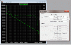
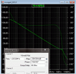
There we go , That's what you DID ! (below 1) is what a gain of 20 will do , unity gain point is 1.2 mhz (should be 570khz) and phase at that point is falling past a safe margin. I would say this amp is "on the edge" (near oscillation).
You could increase the 2 input pair degeneration resistors to 180-220R and up the negative feed back resistor to 22K (gain of @ 25). This will bring you back to 370-400K unity gain crossover with >90 degrees margin. (stable again - below 2)
Wuyit - duhhhh - don't speak before you know , he screwed up the loop gain by changing the design - I re-compensated it for him. This can happen to ANY amp - TMC is less tolerant of insufficient phase margin than CMC (standard miller).
PS - A better way to reduce gain would of been to attenuate at the input and keep the design unchanged.
FIXED!!
OS
Attachments
Last edited:
Just to add, my problems are due to my own silly mistakes causing damage to some other components. The amp sounds brilliant with the BX boards.
I also can't be sure of the ebay 2SA/SC parts I used. I have ordered some MJE parts, as suggested by OS, from Element 14 (Farnell) and will try it again on the weekend.
Then I think I'll call it a day on the amps and concentrate on building my 'mini statements' speakers, which is taking me much longer than I anticipated after having carpal tunnel surgery on both hands
Pete.
Here is the closest approximation of the AX (with cascode) , which is the same as the new DIYA amp. Just DL LT - Linear Technology - Design Simulation and Device Models
Make sure the 2 files in the attached .zip are in the same folder ,click simulate.
OS
Make sure the 2 files in the attached .zip are in the same folder ,click simulate.
OS
Attachments
...click simulate.OS
Hi OS!
What are those peaks at ~1,5MHz and higher?
Do they are spoil the signal with HF furbishes?
Hey OS, just curious, have you ever tried to measure the linearity of an amp's output impedance? To do this, you take a resistor load, and power it with another amp, essentially using the test amp as a virtual ground. Then you measure the distortion of the voltage change at the amp's output. As I understand this is basically a test of the amp's open-loop linearity. I seem to remember Cordell did something similar to test the linearity of opamps, but I may be confused.
- keantoken
- keantoken
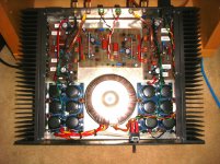
Put the lid on, I'm done
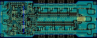
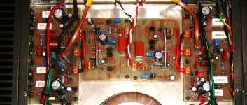
I can finally put the lid on my Mongrel.
It is now complete with all parts as per BOM.
I managed to get trustworthy transistors from Mouser with free postage courtesy of a generous member on stereo.net.au who did a large order down under.
The difference after rebuilding the AX boards is not small, I now know why people say not to trust eBay for semi's.
I have used Panasonic polyprops throughout and FC's for the lytics.
I am running a single 300VA traffo with 60v rails and 6 x 4700uF caps per channel.
Thanks OS for such a nicely designed amp, the sound is brilliant.
Pete.
I can finally put the lid on my Mongrel.
It is now complete with all parts as per BOM.
I managed to get trustworthy transistors from Mouser with free postage courtesy of a generous member on stereo.net.au who did a large order down under.
The difference after rebuilding the AX boards is not small,
I now know why people say not to trust eBay for semi's.I have used Panasonic polyprops throughout and FC's for the lytics.
I am running a single 300VA traffo with 60v rails and 6 x 4700uF caps per channel.
Thanks OS for such a nicely designed amp, the sound is brilliant.
Pete.
Attachments
- Status
- This old topic is closed. If you want to reopen this topic, contact a moderator using the "Report Post" button.
- Home
- Amplifiers
- Solid State
- The MONGREL (supersym II)