By Andrew T. -a. What Re value do you intend to use?
b. What Vre do you think will suit that Re & your output transistors?
c. What is the quiescent dissipation of those output transistors?
To define optimal...
A. .22R is what the design calls for. I have both .22r and .27R. Vbias is stable on both.
B. Vre between 15-17mV for .22R and 17-20mV for .27R.
C. This is quiescent of 65- 80ma per device (150ma for pb60 , 300+ for PB120 600+ for the 250)
I did notice on a undersized heatsink (test heatsink in barn) , Vbias is slightly overcompensated so no safety issues would arise from this. For everyday use or even party use a "proper" full sized unit would be preferred. My stealths are under .1C/w , I use 1 for each 2 pairs on the PB250. on a 30C+ day with 4R heavy use , 43C was the max temp. With days at 20C now , 35C is the norm with very heavy use. Vbias stayed at 17mv /+ - 1mv per device the whole time.
OS
OS,
luvdunhill is cleaning out his parts bin and has some MJL3281A and MJL1302A pairs he is selling to me. The beta is high (75 to 150). Can they be used in the Mongrel? In one of your earlier posts, you specified 25 to 50.
Thanks.
Hi Sonidos,
I used MJL4281/4302 on my Mongrel GX, which has higher gain than 3281/1302 pair.
I measured the Hfes, they ranges from 136 to 156 and the Mongrel GX sounds very good.
I think that OS uses NJW0281/0302 pairs.
Cheers, Stanley
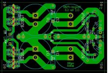
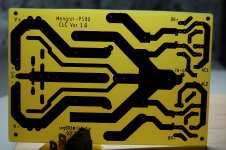
PS100 is a success.
Pix (SS porn) below.
No pits or toner transfer issues. Etched in 6 minutes flat! ALL caps , bridges, inductors fit perfectly. Went from PC to real thing in about 2 hours.
Last 2 pix big inductors 7mH -14 ga. double winding/ 28 turns. Must listen to what a CLC power supply will do.
PS . Apex Jr. Sanwha 8200@100v caps are premium ... leds stayed on for many hours only lost 3 v , no leakage.
OS
Pix (SS porn) below.
No pits or toner transfer issues. Etched in 6 minutes flat!
ALL caps , bridges, inductors fit perfectly. Went from PC to real thing in about 2 hours.Last 2 pix big inductors 7mH -14 ga. double winding/ 28 turns. Must listen to what a CLC power supply will do.
PS . Apex Jr. Sanwha 8200@100v caps are premium ... leds stayed on for many hours only lost 3 v , no leakage.
OS
Attachments
Last edited:
My version of CLC PSU
Hi OS,
I am inspired by your latest PS100 & HackerCap, I will make the followig Mongrel-PS80.
C11 to C14 - Snap-in cap up to 35mm diameter, lead spacing=10mm
D1 to D8 - TO220 diodes such as the MUR1520
D1 to D4 - on a common heatsink, just like the GX1.2VB
D5 to D8 - on a common heatsink, just like the GX1.2VB
I have a bunch of 8200uF/63V snap and MUR1540s, I bought a 0-40/0-40VAC toroid so I can run the PB120+GX at higher rail voltage. It is time to make a new PSU.
Cheers, Stanley
Attachments
Hi OS,
I am inspired by your latest PS100 & HackerCap, I will make the followig Mongrel-PS80.
C11 to C14 - Snap-in cap up to 35mm diameter, lead spacing=10mm
D1 to D8 - TO220 diodes such as the MUR1520
D1 to D4 - on a common heatsink, just like the GX1.2VB
D5 to D8 - on a common heatsink, just like the GX1.2VB
I have a bunch of 8200uF/63V snap and MUR1540s, I bought a 0-40/0-40VAC toroid so I can run the PB120+GX at higher rail voltage. It is time to make a new PSU.
Cheers, Stanley
I have 2 more 8200uF @ 100's left , but only scraps of FR-4 so I might make a
2 cap version with some 8A bridges I have left. Please submit your "PS-80" , I would build it , but have to make 4 PB-60's and some voltage boards with the rest of my material.
I now have some of that "press N' peel blue" (2 sheets)... perhaps a few pointers ??
OS
I have 2 more 8200uF @ 100's left , but only scraps of FR-4 so I might make a
2 cap version with some 8A bridges I have left. Please submit your "PS-80" , I would build it
OS
Hi OS,
The current PS-80 is designed for TO220 rectifiers but I will make provison for external rectifier bridge on the PS-80 PCB. The size of PS-80 is about 125 x 81 mm.
Cheers, Stanley
OS, I would love to join the fun. The PSU looks great! Any updated on your board offerings?
Thanks
A few more fun additions to the PS100 , BTW the PS100 is great sounding, too.
I have been using crippled capacitors now for 2 years and the sonic differences are indeed noticable. My original Nichicon's were absolutely leaking and giving me huge amounts of ripple. Now the Voltage boards are looking at .2-.5MV after the cap multipliers at nuclear volumes...
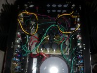
WOW Speaking of nuclear volumes ... with better caps this is a "super luxman" WOW!!
transients are TOTALLY unstrained... my speakers are "scared".
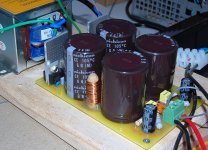
Pix 1- is the whole deal. (super lux).
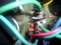
Pix 2- is the bridge between G1 and G2 as Andrew T. advised on... strange ..huh ??
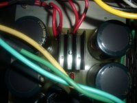
Pix 3- is a vertical output heatsink from an old TV on the main 50A bridge of the PS100 .
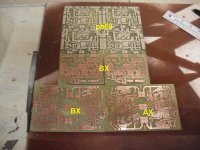
Next you all will see the PB60's (4 - 2 for keen!!) with AX's and BX's (sort of like carlos's blame ES) just my AX with a bootstrapped voltage stage...
I'm in freakin' crazzzy "build mode" .
Board update ... GX is perfect , AX is perfect ., PB250 ,PS100,PB60, all good to go (built and tested).
BX ,my soft start(runs- but need to document it) , and a few more are in the "works".
OS
Attachments
Dang !! ... all those GX's needed to bump them up to the "haunting" level was some "sweeter power". The soundstage is something like I never have even imagined. I can more easily hear the subtle changes as I change the tail currents and main OPS bias now. Ripple is the audiophiles enemy. I wonder how OEM's can get away with 6800uF for a 5 channel setup ... JUNK!!
I did the right "rabbit hole" to dive down a month ago.
OS
... all those GX's needed to bump them up to the "haunting" level was some "sweeter power". The soundstage is something like I never have even imagined. I can more easily hear the subtle changes as I change the tail currents and main OPS bias now. Ripple is the audiophiles enemy. I wonder how OEM's can get away with 6800uF for a 5 channel setup ... JUNK!!I did the right "rabbit hole" to dive down a month ago.
OS
Tips & Tricks for "Press-N-Peel" blue film
Hi OS,
Two Press-N-Peel sheets are good enough for at least half a dozen PB & VB & PS.
The first tip is use the Press-N-Peel like the FR-4, cut the sheet to size of the PCBs.
If the PCB is 8x10cm - cut a 10x12cm portion from the Press-N-Peel sheet (allow at least 1cm margin).
I summarise my procedure here:
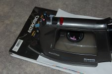
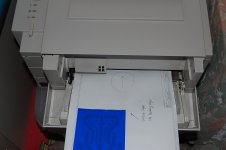
(1) Mark a arrow on a plain paper, use the manual feed to print the PCB artwork onto the plain paper. When I use manual feed, my HP printer prints on the top & that works better.
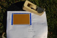
(2) Use Scotch sello tape to stick the leading edge of the pre-cut Press-N-Peel film onto the artwork printout. (You can use the arrow to find out which side is the leading edge).
(3) Put the paper together with the Press-N-Peel film into the manual feed tray, see the attached picture and print the artwork again. Again use the arrow as a guide.
(4) Sandpaper the edge of FR-4 so that it is free of blurs and use some cleaning agent (I use Jif cream) to clean the copper side of the FR-4.
(5) Secure the pre-cut FR-4 onto the Press-N-Peel blue film, I uses masking tape here, any sticky tape will do the job. (It is important to tape all four sides of the FR-4 so that the film does not move during the ironing).
(6) Use a standard iron (dry medium heat for 5 minutes) to transfer the toner onto the FR-4. Printout on top, pay extra attention to the edge of the PCB.
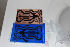
(7) Put the paper & FR-4 into cold water for 1 minute. Remove the masking tape & peel off the Press-N-Peel film.
(8) If there are pin holes on the FR-4, use permanent marker pen (I use Toyo "Name" Oil-base Pen) to patch the pin-holes.
(9) Etch the FR-4 with your favourite etching chemical.
The only shortfall is the masking tape leaves some sticky residues on the FR-4 but that can be dealt with after the etching. The advantage of using the Press-N-Peel is the resolution is better & the Blue film fills the microscopic pits in the standard toner & I normally do not pre-tin the PCBs.
Cheers, Stanley
I now have some of that "press-N-peel blue" (2 sheets)... perhaps a few pointers ??
OS
Hi OS,
Two Press-N-Peel sheets are good enough for at least half a dozen PB & VB & PS.
The first tip is use the Press-N-Peel like the FR-4, cut the sheet to size of the PCBs.
If the PCB is 8x10cm - cut a 10x12cm portion from the Press-N-Peel sheet (allow at least 1cm margin).
I summarise my procedure here:
(1) Mark a arrow on a plain paper, use the manual feed to print the PCB artwork onto the plain paper. When I use manual feed, my HP printer prints on the top & that works better.
(2) Use Scotch sello tape to stick the leading edge of the pre-cut Press-N-Peel film onto the artwork printout. (You can use the arrow to find out which side is the leading edge).
(3) Put the paper together with the Press-N-Peel film into the manual feed tray, see the attached picture and print the artwork again. Again use the arrow as a guide.
(4) Sandpaper the edge of FR-4 so that it is free of blurs and use some cleaning agent (I use Jif cream) to clean the copper side of the FR-4.
(5) Secure the pre-cut FR-4 onto the Press-N-Peel blue film, I uses masking tape here, any sticky tape will do the job. (It is important to tape all four sides of the FR-4 so that the film does not move during the ironing).
(6) Use a standard iron (dry medium heat for 5 minutes) to transfer the toner onto the FR-4. Printout on top, pay extra attention to the edge of the PCB.
(7) Put the paper & FR-4 into cold water for 1 minute. Remove the masking tape & peel off the Press-N-Peel film.
(8) If there are pin holes on the FR-4, use permanent marker pen (I use Toyo "Name" Oil-base Pen) to patch the pin-holes.
(9) Etch the FR-4 with your favourite etching chemical.
The only shortfall is the masking tape leaves some sticky residues on the FR-4 but that can be dealt with after the etching. The advantage of using the Press-N-Peel is the resolution is better & the Blue film fills the microscopic pits in the standard toner & I normally do not pre-tin the PCBs.
Cheers, Stanley
Attachments
Last edited:
Hi Os,
what is it like getting used to thinking of the amplifier as a modulator between the PSU and the Speaker?
It's the same adage as, the amp can only be as good as the PSU.
When you get to measuring the amp, could you compare the G1 to G2 to the usual method of connecting the ground trace serially though the PSU.
Does the output ripple change in any way, ripple, spikes, charging pulses, etc?
Hi Os,
what is it like getting used to thinking of the amplifier as a modulator between the PSU and the Speaker?
It's the same adage as, the amp can only be as good as the PSU.
Absolutely , Andrew ! "Wire with gain" can only be as good as what flows through the wire. To think I was amplifying ripple was disconcerting. Your grounding tips were also a realization... Johnson–Nyquist noise is all that is left. Tightly pressing an ear to a midrange to hear ANYTHING is the best I've done to date. You have to go to the .1mV range on the scope to barely see it , also absolutely NO (V)HF components (oscillation) on either the AX or GX.
About the only way to improve now is the source. In my case a nice DAC for optical coupling from sound card to mongrel would be nice ... maybe I can do another neeto "swap meet deal"
.OS
Updates on PS-80
Hi OS,
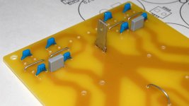
I spend much of the last weekend fiddling with the PS-80. I made a couple of mistakes in the layout and that was fixed with a Stanley knife.
The four jumpers wire must be installed first as they sit between the TO-220 diodes. The mounting of the TO-220 diodes were tricky & I fixed the diodes onto the small heatsink before I soldered them onto the PCB.
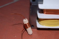
I found a new way (for me anyway) to make inductor - I found a few flueted wood dowels(8mm dia.) and used them as the coil former. I drilled two small holes at one end and one hole on the other end. I started the coil from the end with two holes. When the winding reach the other end, I threaded the magnet wire thru the hole & tightened it. I then started the return windings and thread the magnet thru the second hole at the starting end. The inductor coil is two layers & about 30 turns in total with 0.9mm (AWG19) magnet wire (salavaged from a broken transformer).
I guessed that if I used some exotic wood & encapasulated them in epoxy and put the GM logo on it and I can sell it for thousand dollars a piece.
I used a short wire in place of the R5 to connect G1 to G2.
Listening test: the new PS80 (C-L-C) sounds slightly better than the old C-C PSU (I used a 4.7R to the connect G2 to the star ground of the C-C PSU) and both PSUs use the same transformers & capacitors. The result is subjective as it is quite time consuming to do "back-to-back" listening tests.
Some pictures:
I have 2 more 8200uF @ 100's left , but only scraps of FR-4 so I might make a
2 cap version with some 8A bridges I have left. Please submit your "PS-80" , I would build it , but have to make 4 PB-60's and some voltage boards with the rest of my material.
OS
Hi OS,
I spend much of the last weekend fiddling with the PS-80. I made a couple of mistakes in the layout and that was fixed with a Stanley knife.
The four jumpers wire must be installed first as they sit between the TO-220 diodes. The mounting of the TO-220 diodes were tricky & I fixed the diodes onto the small heatsink before I soldered them onto the PCB.
I found a new way (for me anyway) to make inductor - I found a few flueted wood dowels(8mm dia.) and used them as the coil former. I drilled two small holes at one end and one hole on the other end. I started the coil from the end with two holes. When the winding reach the other end, I threaded the magnet wire thru the hole & tightened it. I then started the return windings and thread the magnet thru the second hole at the starting end. The inductor coil is two layers & about 30 turns in total with 0.9mm (AWG19) magnet wire (salavaged from a broken transformer).
I guessed that if I used some exotic wood & encapasulated them in epoxy and put the GM logo on it and I can sell it for thousand dollars a piece.
I used a short wire in place of the R5 to connect G1 to G2.
Listening test: the new PS80 (C-L-C) sounds slightly better than the old C-C PSU (I used a 4.7R to the connect G2 to the star ground of the C-C PSU) and both PSUs use the same transformers & capacitors. The result is subjective as it is quite time consuming to do "back-to-back" listening tests.
Some pictures:
Attachments
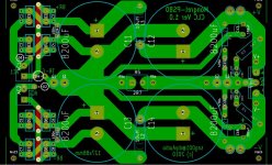
Mongrel-PS80 PCB file
Hi,
I have put the PCB layout & a few pictures into the attached PDF file. The layout has been debugged & I made the board slightly bigger (127x88mm).
I included two versions of the copper layer, one with small drill marks & the other with the normal hole size. I prefer the small drill marks version but it need higher resolution in the etching process.
The board also cater for center-tapped transformer & you need to mount 4 diodes.
Externally-mounted rectifier bridge can also be used, just connect transformer centre-tap to G1; BR+ & BR-.
Cheers, Stanley
Attachments
Last edited:
amp is 1KVA/ + - 75V which can kill easily
if these go together then that is just 13% losses from fully charged PSU to Maximum output voltage. That's a good result. Now see what short term voltage it can pass to 2r6. This will indicate how well it meets current demand.Does 100v P/P with the greatest of ease. into a 8R load scoped 130v p/p for a short while
that surprises me.
An 8ohm capable amplifier must be able to drive an 8ohm speaker.
The stress of driving an 8ohm amplifier is similar to driving a 2r6 resistor.
I see that Bob Cordell also uses the three times rule for what he has termed Ireserve.
If your amp cannot survive a few seconds into one third of rated resistive loading then in my opinion it cannot be rated correctly in the first place.
BTW,
a few seconds is sufficient to pull down the PSU to full sag and to pass what is effectively a continuous sinewave test signal while the output stage is still fairly close to normal operating temperature. Do Not let the output or driver devices get hot! That may over-stress the amplifier into a 2r6 resistive load.
PS.
have you used Bensen's spreadsheet to assess the de-rated SOAR for your output stage?
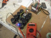
#1 - I don't have a 2.6R load available. #2 - I am scared to do it , the tests I did do made those huge stealth heatsinks HOT. BTW my DMM read 71v positive rail at the 130v test. I did this to see if my cap multipliers were performing par excellance (4-5 mv ac at that level) almost as good as having a separate supply.
I didn't do the spreadsheet , I approximated by ON's SOA plot (5A -- infinite ,8A- 100mS >10A 10ms ... 4/ NJW0281).
For musical content , I really did use a paralleled pair per channel (4 loudspeakers total) , what surprised me (not really) is that my heatsinks were not as hot with MUSIC/ 2pair as with a continuous sine input/8R. On a 35C day , the amp sustained 2 hours british heavy metal before law enforcement was called.
The sound pressure levels at 10 ft. were enough to vibrate the extra fat on my body or a glass of water had standing waves in it (coffee). ALL objects had to be removed in a 20' radius while the most subtle details (breath , fingers on strings) were very audible and detailed. A clap was a clap and a snap was a snap (audiophool test.)
OS
Last edited:
Wow , I didn't see that, SNG. Cool small "little brother" to PS100.
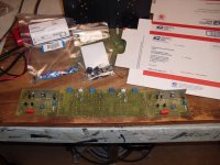
Later today I will do the whole PB60/AX - BX thing , have patience KEEN , I want to run these before stuffing them in postal box . I had to build them first (PB60's).
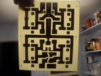
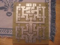
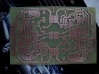
One thing , the press and peel , fab in a box , all better if you have a good laminator. For just ironing , the high gloss , high clay content magazine page toner transfer method is way better. (pix 1 /2) NO pits before tinning. REAL good after tinning.
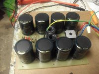
(tip) tin with 35% cu/ 65% sn lead free , this will increase 1 oz to over 2 oz. conductivity wise. I use plain ol' plumbers flux , wash off board with good household cleaner after. (pix 2) is of the "new " amps (pb60 / ax/bx).
OS
small "little brother" to PS100.Later today I will do the whole PB60/AX - BX thing , have patience KEEN , I want to run these before stuffing them in postal box . I had to build them first (PB60's).
One thing , the press and peel , fab in a box , all better if you have a good laminator. For just ironing , the high gloss , high clay content magazine page toner transfer method is way better. (pix 1 /2) NO pits before tinning. REAL good after tinning.
(tip) tin with 35% cu/ 65% sn lead free , this will increase 1 oz to over 2 oz. conductivity wise. I use plain ol' plumbers flux , wash off board with good household cleaner after. (pix 2) is of the "new " amps (pb60 / ax/bx).
OS
Attachments
- Status
- This old topic is closed. If you want to reopen this topic, contact a moderator using the "Report Post" button.
- Home
- Amplifiers
- Solid State
- The MONGREL (supersym II)