Left R28 : 0.4 / 0.48
Right R28 : 0.3 / 0.46
clarify
All inputs gathered together + - g (balanced)
No load at the output.
So let say I've got :
R27 and R28 are 0R47
Left R27 = (14.1-13.76)/.47 = 0.914A
Left R28 = (0.05-0.5)/.47 = 0.957A
Right R27 = (14.21-13.77)/.47 = 0.936A
Right R28 = (0.04-0.49)/.47 = 0.957A
Correct ?
No load at the output.
So let say I've got :
R27 and R28 are 0R47
Left R27 = (14.1-13.76)/.47 = 0.914A
Left R28 = (0.05-0.5)/.47 = 0.957A
Right R27 = (14.21-13.77)/.47 = 0.936A
Right R28 = (0.04-0.49)/.47 = 0.957A
Correct ?
Last edited:
proper measurement across resistor is not measuring both ends against GND as reference, but measuring directly across resistor
one probe one resistor end, second probe other resistor end
though , you got it, even if in longer way
you're good with everything for Mini A - both Iq and output DC offset
sole thing with which you can play is - changing Aleph CCS AC gain , and that you can do with changing value of R12 (ref to your schematic in post #1036)
vary it in steps/standard values** up to 1K5 ( logically both channels same), listen some time with one value , make notes and put most liked value for good
no other adjustments needed, value of that resistor is not influencing any static value
**820R, 910R, 1K, 1K2, 1K5
not exactly need for measurement, because you need to decide with ears which value you like most
though, put some sine (few volts, no need for more), 400Hz to 1KHz (higher can confuse your DVM), dummy load on output
measure AC voltage across R27, then across R28
write down ; their ratio is showing how much each half of amp is contributing to output
though, put some sine (few volts, no need for more), 400Hz to 1KHz (higher can confuse your DVM), dummy load on output
measure AC voltage across R27, then across R28
write down ; their ratio is showing how much each half of amp is contributing to output
Work in progress.
I reduced BrianGT PSU resistor value from 0R51 to 0R14.
I've read this should improve higher voltage but reduce rejection.
Added Mark Johnson "Quasimodo" filter, according from other members reported values.
This should reduce transfo ringing. I've got no scope, nor search more about how to measure values with DMM.
Read a useful doc about distortion and biasing : https://www.firstwatt.com/pdf/art_leave_classa.pdf
Tomorrow I'll replace R12, from 750R to 1K.
Need to remove amps boards to solder the new resistor.
Found 1K, 1K2 and 1K5 values.
(R12 : AC Gain - R13 : Biasing - R8 : DC Offset according to Algar emi schematic)
Will hear and take notes after R12 change.
Thanks Zen Mod
Attachments
Last edited:
Hi there,
Replaced R12 from 750R to 1K : desolder resistors, dismount boards and Fets.
Checked everything around, added previoulsy posted filter to BrianGT PSU input.
And let's go, no smoke, music plays on : there's something really better, more refined.
Need time to taste the new flavor a bit before upgrading to 1K2.
Values using Balanced Input - Speaker load at the output let say around 8Ohms/93dB.
I've got, no signal playing :
Left R27 = 14.66-14.23
Left R28 = 0.037 - 0.46
Right R27 = 14.63-14.20
Right R28 = 0.015 - 0.43
The DC voltage increase (.5V) seems doing nice things to my ears.
A little bit more heat on heatsinks, but fine at least.
Preamp volume sets to -30dB, music volume is quite enough.
Comments are welcome
Thank's
Last edited:
Good morning all,
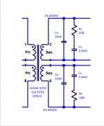
I purchased two Pass-AM cards from Sheffield Audio (Chinese).
The cards are well made with some good components and some really poor quality. Result, the card comes out with an offset of 94mV.
They used 8 poor quality carbon resistors with values very far from the nominal values (example: 340R for 220R marked).
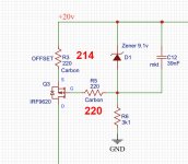
To start, I changed the DC offset resistors (R3 / R5) and goes to 25mV.
What did you think of this use of carbon resistors by the designer?
Stephane
IRF9620 are marked Fairchild.
IMG-5676 — ImgBB

Not easy to trace a double side pcb.
Schematic-PASS-AM-2021-05-20 — ImgBB

I purchased two Pass-AM cards from Sheffield Audio (Chinese).
The cards are well made with some good components and some really poor quality. Result, the card comes out with an offset of 94mV.
They used 8 poor quality carbon resistors with values very far from the nominal values (example: 340R for 220R marked).
To start, I changed the DC offset resistors (R3 / R5) and goes to 25mV.
What did you think of this use of carbon resistors by the designer?
Stephane
IRF9620 are marked Fairchild.
IMG-5676 — ImgBB
Not easy to trace a double side pcb.
Schematic-PASS-AM-2021-05-20 — ImgBB
Last edited:

Only some resistors to replace. The rest seems ok.
If you have any advice on values that would be incorrect in the diagram I posted?
The online version. Some changes.
PASS-AM - EasyEDA open source hardware lab
If you have any advice on values that would be incorrect in the diagram I posted?
The online version. Some changes.
PASS-AM - EasyEDA open source hardware lab
Good morning all,
I purchased two Pass-AM cards from Sheffield Audio (Chinese).
The cards are well made with some good components and some really poor quality. Result, the card comes out with an offset of 94mV.
They used 8 poor quality carbon resistors with values very far from the nominal values (example: 340R for 220R marked).
To start, I changed the DC offset resistors (R3 / R5) and goes to 25mV.
What did you think of this use of carbon resistors by the designer?
Stephane
IRF9620 are marked Fairchild.
IMG-5676 — ImgBB
https://ibb.co/FhQHNHS
Not easy to trace a double side pcb.
Schematic-PASS-AM-2021-05-20 — ImgBB
https://ibb.co/nCFZdrj
Hello Friend. I can tell you something: if you think this amplifier has a problem, you should be more suspicious of the transistors than the resistors.
Hello Carlos,
At the moment, I don't think transistors have a problem. By contrast, after having unsoldered and checked each resistance, I can tell you that they are very far from nominal values.
For the moment, I just changed the resistors which control the offset and the result is spectacular. They was 240R and 340R. I replaced with 220 and 214. I went from 94mV offset to 4.5mV.
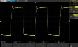
On the other hand, the measurements at the scope are not good. Square signals are distorted.
I ordered the resistances which I miss. Afterwards, I would take care of redoing the measurements and worrying about the transistors if there are still problems.
Cheers,
Last schematic version with component placement: PASS-AM - EasyEDA open source hardware lab
At the moment, I don't think transistors have a problem. By contrast, after having unsoldered and checked each resistance, I can tell you that they are very far from nominal values.
For the moment, I just changed the resistors which control the offset and the result is spectacular. They was 240R and 340R. I replaced with 220 and 214. I went from 94mV offset to 4.5mV.
On the other hand, the measurements at the scope are not good. Square signals are distorted.
I ordered the resistances which I miss. Afterwards, I would take care of redoing the measurements and worrying about the transistors if there are still problems.
Cheers,
Last schematic version with component placement: PASS-AM - EasyEDA open source hardware lab
Attachments
Last edited:
- Home
- Amplifiers
- Pass Labs
- The Mini-A