I see a few things you can improve
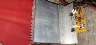
"L" profile not properly bolted to the main heatsink
"L" profile to wide and thin - get mosfets closer to the main heatsink or on the it (remove ""L" profile
Place the heatsink vertically to help heat evacuation (improve air flow)
And you are measuring the temp on the body of the mosfet and that will give you higher readings
Not been critical just a few things that can help with your issue.
Wouldn't it be correct to measure the temperature directly on the transistor as the temperature flows from it to the aluminum? I would like to know the measurements of the friends if possible directly on the transistors to see if the difference is very big (it would be nice). Tomorrow I will measure the temperature with the two heatsinks connected in two ways: on the transistor and on the heatsink.
@andcarlos - stand the heatsink so that the fins are vertical and put something underneath it so that air can flow from below and out the top. I'm certain that if you do just this alone you will see temperature drop as the way you have it currently, it's not good at all for airflow over the fins.
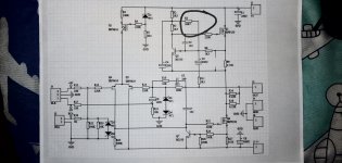
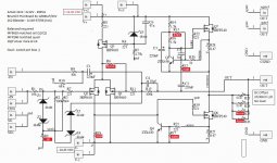
Do you have a schematic for that board ?
Can you adjust bias (I see 2 trimmers) ?
You still use that thin "L" profile did you use thermal paste ?
Measure temp on the heat sink on the Mosfet the temp is much higher.
And remember that the more aluminium pieces you use on your setup the lower the efficiency (if they are not properly bolted together).
You cold just had remover the "L" and put the Mosfet directly on the main heatsink foe testing.
Yes. This resistor that was circulated there was replaced by a 10k trimpot. The output resistors were all replaced by the original values. The sinks were lying down but I already placed them upright. The temperature in them was 41 ~ 42 degrees Celsius. When I put the thermometer on top of the outlets, the temperature rises to 65 degrees Celsius.
Attachments
Last edited:
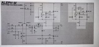
Compare your schematic with the original or the one from P Daniel boards and you will see that the values don't add up (it doesn't mean it will not work).
Temp wise you are fine if your headsinks stay at around 40-45C the difference between mosfets and heatsink is normal and to be expected.
On your Bias problems you will have to sort it with the people that sold you that board or by someone here willing to help you in that department.
R13 = 47.5K your R3 = 56K
R12 = 750R your R11 = 1K5
And many others
Attachments
Last edited:
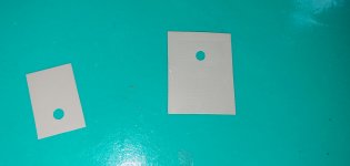
I've already made all the changes to make the circuit look the same as the original. I even changed the transistors that are attached to the irfp240. Today I did several tests and the temperature seems normalized. I replaced the thermal pads with mica and the heat transmission is more efficient. I also placed the sinks upright but before changing the cushions the temperature had not dropped and this only happened after I made the exchange for mica. Just to correct the value of the variable resistor: it is 20k and not 10k (sorry for the error). Transistor body temperature: 68 to 72 degrees Celsius. Temperature on large sinks: 48 degrees Celsius. I believe that it is now normal. These pads in the photo are the ones I took (they are found in computer sources and are very bad at transmitting heat): happy1:
Attachments
Last edited:
I managed to find the heatsink I was looking for
I managed to find the heatsink I was looking for. I will join two of him through a corner. It will work because the other channel has already been tested and the temperature in the heatsink was stable at 42 ° with the current set to 1.1A. The transistor body was stable at 62 °. Each heatsink has 0.94 ° C / W of thermal dissipation and joining two of these is 0.47 ° C / W.")
I managed to find the heatsink I was looking for. I will join two of him through a corner. It will work because the other channel has already been tested and the temperature in the heatsink was stable at 42 ° with the current set to 1.1A. The transistor body was stable at 62 °. Each heatsink has 0.94 ° C / W of thermal dissipation and joining two of these is 0.47 ° C / W.

@MEGA_amp
John, thanks a lot. I can see the boards en route in mail. Just wanted to acknowledge here your generosity for not even asking for the shipping cost so I donated to DIYaudio instead. Thx again.
View attachment 928913
Awesome! I'm a firm believer that every home should have at least one Aleph.

I though I should repost here my question of going mini with Aleph J version:
https://www.diyaudio.com/forums/pass-labs/176857-semisouth-aleph-21.html#post6602168
https://www.diyaudio.com/forums/pass-labs/176857-semisouth-aleph-21.html#post6602168
MiniA BrianGT Boards (PSU/Amp)
Hi all,
I'm looking for some guidance for a Mini A built from BrianGT boards (PSU/Amp).
My electronic skill is weak, I've got 1 DMM, soldering fine.
Master Zen Mod seems to be the required Wizard for this kind of search
You'll find attached schematic with informations.
Amp is working with no load, measures could be performed on demand !
My goal is to make it sound right with described parts.
I've read some hints here and there :
- R14/R16 reduced form 1K5 to 750R
- R27/R28 reduced from 0R47 to 0R22
- R12 sets current gain (750R)
- R13 sets Bias voltage (47K5)
- R18 is DC offset (390R)
Where to begin first ?
Thanks for your help
Attachments
No trouble it works, but flawlessly.
From what I've read there are some punch missing to get the "sweet pot".
This could be achieved by increasing biasing and don't know how with my parts/values.
What sould I measure to have the informations like actual Bias ?
From what I've read there are some punch missing to get the "sweet pot".
This could be achieved by increasing biasing and don't know how with my parts/values.
What sould I measure to have the informations like actual Bias ?
Last edited:
Some measures made, amp connected for 2 hours.
Left Q6 : 9.16 / 00.04 / 13.74 (G D S)
Left Q7 : 5.10 / 14.17 / 00.49 (G D S)
Right Q6 : 9.27 / 00.04 / 13.70 (G D S)
Right Q7 : 5.00 / 14.21 / 0.47 (G D S)
Left R28 : 0.4 / 0.48 - Left R27 : 13.77 / 14.21
Right R28 : 0.3 / 0.46 - Right R27 : 13.76 / 14.19
DC Offset : L 48mV / R 33mV
PSU DC : +14.26 / -14.24
Thank you for comments
Last edited:
Read a lot about MiniA, and some hints :
- Replace R8 (221R) with Trim 500R - DC Offset
- Replace R12 (750R) with Trim 2K - AC Gain
- Replace R13 (47K5) with Trim 100K - Bias Current
Source : Mini Aleph Build post #89
I'll have a look if have those around...
Someone to confirm ? Thanks
- Replace R8 (221R) with Trim 500R - DC Offset
- Replace R12 (750R) with Trim 2K - AC Gain
- Replace R13 (47K5) with Trim 100K - Bias Current
Source : Mini Aleph Build post #89
I'll have a look if have those around...
Someone to confirm ? Thanks
- Home
- Amplifiers
- Pass Labs
- The Mini-A