For dual driver/bipole cab alignments it's basically a 2x Vas calculation, so 2x a single driver cab's cross sectional area [CSA] and use the mean for a 'close enough' compromise option for either.
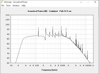
Fascinating. So, here's what I get when I simply double So and Sl of the original scottmoose CHN110 design and add another speaker (the graph has the original design with one speaker, vs bipole speakers in 2x sized metronome:
What stands out to me is that the bipole graph in a 2x sized metronome is a spitting image of monopole in a 1x sized metronome, just 6db louder.
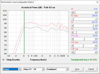
Now, let's try your suggestion of "close enough compromise" cabinet, using the average (1.5x So and Sl dimensions)
Looks good, but a bit different: A slightly "softer" knee at the tuning frequency, and slightly more exaggerated ripples above 1kHz. I have no idea what impact this has on the sound, but it looks within a couple db at every point when compared to the full-size 2x bipole.
Interestingly, in my "playing around with hornresp" design, I got an Sl that is prety close to this compromise design: 900 cm^2 in my design, vs 957 cm&2 in this compromise design.
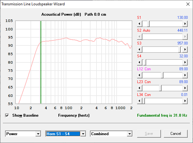
However, my design used a smaller top area (So of 64 cm^2), vs the 195 cm^2 of this compromise design. If I shrink the top area of the metronome in the compromise design, and re-tune to the same Fb, I get a very similar graph:
It looks a little softer around the tuning frequency, but what really stands out is the increasing amplitude of the wiggles above 1kHz.
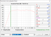
Out of curiosity, I shrunk the top area (So) even more to 8 cm^2:
Now the curve at Fb looks even softer, and seems to be developing a minor hump. The resonance bumps at the other end of the spectrum look even more extreme, and the phenomenon can be seen at 700Hz instead of 1kHz.
Can anybody comment on the possible sound quality/character implications of the various tweaks to the original cabinet design?
Specifically, it it likely the 1.5x "compromise" cabinet size would not sound much different in real life than the full-sized 2x bipole cabinet size?
Additionally, is changing the taper and re-tuning a viable degree of freedom one could tweak for aesthetic purposes without affecting the resulting sound too substantially? The primary area of concern from the graphs as far as I can tell is the appearance of a little "hump" at extreme tapers (which may or may not be significant), and the increasing "squiggles" in the response curve above 1kHz (which may not be audible and/or may not escape the cabinet in real life).
Attachments
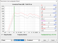


What stands out to me is that the bipole graph in a 2x sized metronome is a spitting image of monopole in a 1x sized metronome, just 6db louder.
Looks good, but a bit different: A slightly "softer" knee at the tuning frequency, and slightly more exaggerated ripples above 1kHz. I have no idea what impact this has on the sound, but it looks within a couple db at every point when compared to the full-size 2x bipole.
Specifically, it it likely the 1.5x "compromise" cabinet size would not sound much different in real life than the full-sized 2x bipole cabinet size?
Additionally, is changing the taper and re-tuning a viable degree of freedom one could tweak for aesthetic purposes without affecting the resulting sound too substantially?
Like I said........
")
Doubtful, even if compared side by side outdoors, though in room you might notice a slight tonal difference in some parts of a solo due to room modes variances and even then probably only if you're a musician trained in such minutiae and/or have bat hearing like some young women I've known that 'voiced' my designs.
Down below ~200 Hz, no way.
The room will mod it more than some minor taper changes and even major ones just changes vent tuning, internal damping. Regardless, when designing any high aspect ratio cab it should be based on the [HF] driver's desired ear height.
Thanks, this was very helpful. Walking through the simulations to see how it correlated with advice was a good learning exercise.
One more thing. I was watching a lecture the other day by Dr. Scott Lindgren, and there was a fascinating section about how some non-flat curves can better integrate with a room, when accounting for room gain. The technique discussed in the lecture pertains to bass-reflex boxes, and involves slightly under-sizing and low-tuning a box, resulting in a broad, soft low-frequency shelf.
Dr. Scott Lindgren talking speaker enclosure design (part 2) - YouTube
Hornresp modeling suggests you could easily do the same technique to a metronome. Here's a "compromise" 1.5x bipole metronome using the scottmoose chn-110 aliment as a starting point, increasing the bottom CSA by 1.5x, increasing the taper (purely for aesthetics, leaving the top a little more narrow), adding another driver (bipole), then tuning lower.
So.. would something like that integrate fairly well into a room? It was incredibly easy to achieve merely by tuning.
I'm seeing that the metronome is an incredibly flexible, resilient, and adaptable design. At this point, I'm becoming increasingly confident it can be made to work well, with a little port tuning after the fact.
Attachments
It really depends on the room modes, boundary gain with the theoretical/practical ideal is a 0.707 Qtc' sealed, i.e. 12 dB/octave slope, coupled to the room's ideal 12 dB/octave rise = flat to the room's lowest frequency [SoS/2/longest parallel room dimension] or net volume [Vb] pressurizing limit of the speaker such as the serious gains down into the single digits that high tuned sealed speakers can attain in well constructed vehicles, bomb shelters, etc..
From this we see that mimicking this in vented is a good plan if the room is small and/or corner loaded = extended bass shelf [EBS] alignment is preferred and all the truly low tuned cabs I've done were EBS, though wasn't aware it had a name and even has a [bit too restrictive IME] proper T/S design routine until I got on the forums.
From this we see that mimicking this in vented is a good plan if the room is small and/or corner loaded = extended bass shelf [EBS] alignment is preferred and all the truly low tuned cabs I've done were EBS, though wasn't aware it had a name and even has a [bit too restrictive IME] proper T/S design routine until I got on the forums.
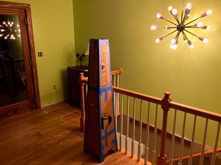
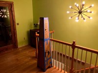
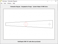
OK, I have four CHN-110 drivers on order for bipole metronomes! I made a cardboard mockup this past weekend. Based purely on aesthetics, we landed on a shorter design (57" chamber height, 61" total speaker height), which hornresp suggests will be quite workable.
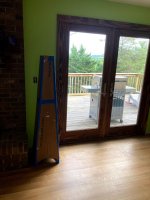
Anyway, here is the primary position they'll be in, for bipole operation:
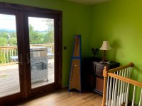
.. and a potential positioning for monopole operation:

In bipole mode, any tuning between roughly 30 and 38 Hz looks quite decent
In monopole mode, it looks like it's happier with some stuffing in the lower portion of the cone, below the driver. Moving it between modes will be rare, will have to play with it to see if it needs a removable panel to add more stuffing when necessary:
Finally, it looks like this alignment is happy with the drivers situated a few inches above or below the midpoint of the chamber. The curves are especially smooth when the driver is situated down low (33 inches from the top, 24 inches from the bottom). So... maybe I'll try offsetting the front and rear drivers?
Thanks for the help! Will start building later on in the summer.
Anyway, here is the primary position they'll be in, for bipole operation:
.. and a potential positioning for monopole operation:
In bipole mode, any tuning between roughly 30 and 38 Hz looks quite decent
In monopole mode, it looks like it's happier with some stuffing in the lower portion of the cone, below the driver. Moving it between modes will be rare, will have to play with it to see if it needs a removable panel to add more stuffing when necessary:
Finally, it looks like this alignment is happy with the drivers situated a few inches above or below the midpoint of the chamber. The curves are especially smooth when the driver is situated down low (33 inches from the top, 24 inches from the bottom). So... maybe I'll try offsetting the front and rear drivers?
Thanks for the help! Will start building later on in the summer.
Attachments
Cool graphics!
FYI/FWIW, theoretically ideal driver offset for a quadratic horn is ~0.424-0.56 offset depending on taper, and using HR you'll see this by temporarily removing any stuffing and in the 'power' window, go to 'chamber' and slide the 'path-length' along till all the dips are gone with just a bunch of high Q spikes left [usually ~the distance to the bottom + vent length].
Now you'll need much less damping and have a better idea of what the driver/port blending will sound like at the LP.
Last edited:
I've been making little tweaks to the design, which I'll create a new thread for at some point. In the course of doing so, I noticed that one can model a metronome in two different ways in hornresp, with some subtle (but real) differences: with an external port, and with an offset port. It's hard to describe in words, so here are some pictures.
"External" starts from the standard mass-loaded transmission line profile in hornresp, and looks like this:

"Offset port" uses the offset-port mass-loaded transmission line profile in hornresp, and looks like this:
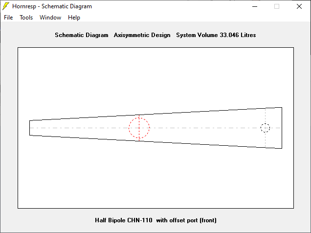
The controls are different for "offset port" - you essentially specify port length, area, and distance along the transmission line.
Now, the metronome doesn't have a hole in its side, as its port fires downward. HOWEVER, for ports that are longer than the thickness of the cabinet, the port will be a pipe that sticks up into the internal volume of the speaker. My question is: Is it more accurate to model the metronome port as an "offset" port, whereby the offset distance is equal to the length of the port tube (i.e. reflecting the fact that the inlet is a few inches above the bottom of the cabinet)?
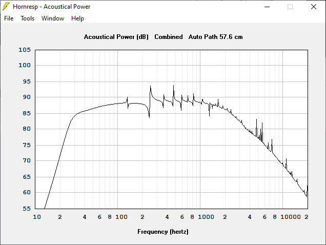
The resulting SPL curves differ in noticeable ways. The offset profile results in much less ripple (this can be optimized), resulting in much less stuffing needed to get nice-looking curves. This seems to better match firsthand reports in this thread, whereby minimal stuffing seemed to result in optimal performance. Additionally, one can set the Ql (leakage) value for the "offset port" profile - an option that is unavailable as far as I can tell for the standard MLTLprofile in hornresp. From the looks of it, Ql very high (no leakage) in the standard MLTL profile. Setting a realistic Ql makes a difference in the resulting curves.
Here's a comparison of two raw curves of the same metronome, modeled with an "external" port (standard MLTL configuration) vs "offset" port (offset port configuration). A Ql of 15 was chosen the "offset" model. The second (cleaner) one is the results of "offset port" model.

"External" starts from the standard mass-loaded transmission line profile in hornresp, and looks like this:
"Offset port" uses the offset-port mass-loaded transmission line profile in hornresp, and looks like this:
The controls are different for "offset port" - you essentially specify port length, area, and distance along the transmission line.
Now, the metronome doesn't have a hole in its side, as its port fires downward. HOWEVER, for ports that are longer than the thickness of the cabinet, the port will be a pipe that sticks up into the internal volume of the speaker. My question is: Is it more accurate to model the metronome port as an "offset" port, whereby the offset distance is equal to the length of the port tube (i.e. reflecting the fact that the inlet is a few inches above the bottom of the cabinet)?
The resulting SPL curves differ in noticeable ways. The offset profile results in much less ripple (this can be optimized), resulting in much less stuffing needed to get nice-looking curves. This seems to better match firsthand reports in this thread, whereby minimal stuffing seemed to result in optimal performance. Additionally, one can set the Ql (leakage) value for the "offset port" profile - an option that is unavailable as far as I can tell for the standard MLTLprofile in hornresp. From the looks of it, Ql very high (no leakage) in the standard MLTL profile. Setting a realistic Ql makes a difference in the resulting curves.
Here's a comparison of two raw curves of the same metronome, modeled with an "external" port (standard MLTL configuration) vs "offset" port (offset port configuration). A Ql of 15 was chosen the "offset" model. The second (cleaner) one is the results of "offset port" model.
Attachments


Yes, where the pipe terminates vertically is where it should be in the offset, otherwise the internal floor reflection isn't accounted for.
The external pipe can be damped to 'taste' same as the rest of the cab whereas the offset one is adjustable based on QL theory, so you can adjust the offset vent damping to find what stuffing density = 'x' QL.
The external pipe can be damped to 'taste' same as the rest of the cab whereas the offset one is adjustable based on QL theory, so you can adjust the offset vent damping to find what stuffing density = 'x' QL.
I had an idea about how to design a metronome style tapered cabinet but with a 7 degree linear taper. I'm not sure how tapers are calculated but i assume they are multiplied together in two dimensions, e.g. a voigt pipe is 7 degrees and a metronome is 7x7 or 49 degree taper.
so to do a metronome with a 7 degree taper then the sides would be at 2.5 degrees or so, which is likely no good to avoid resonances, too close to parallel.
then i thought that the small end could be made larger in one dimension, and the large end smaller in another dimension. that way you get away from parallel sides.
so here's a mockup of what it would look like.
Attachments
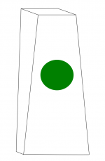
What matters is not the taper but the change in cross sectional area. And the change in cross sectional area become hyperbolic (for the sake of simplification) once there are 4 sides that are tapering.
Plus, the relationship between taper angle and cross sectional area change is not linear, but trigonometric
Plus, the relationship between taper angle and cross sectional area change is not linear, but trigonometric
Horn tapers are referenced to the object's radial axis [down the middle], so 3.5 deg each side for 7 deg included and since it doesn't meet the >12 deg included angle its 'slap echo' won't completely decay away.
For the Metronome's quadratic taper, the taper is in two planes [pyramid].
No clue what, if any, name applies to your variant or why one would build it except for uniqueness as an architectural 'statement'.
For the Metronome's quadratic taper, the taper is in two planes [pyramid].
No clue what, if any, name applies to your variant or why one would build it except for uniqueness as an architectural 'statement'.
 Good specs for positive tapered TLs [ML horn], so imagine it will perform demonstratively better than your originals.
- Home
- Loudspeakers
- Full Range
- The Metronome