Re: Trying to focus the controversy
Rodolfo,
I agree, but I like to add that this is a gradual difference, not a principled one. In my audio life I had numurous occasions thinking: ahh, NOW I understand, only to find another layer of complexity below what I knew. Its like an onion. When you have peeled off a layer of skin, you think you see what's inside. Not so, you see .. another onion!
The difference in experience and education in these forums' members is that they are at different layers in the onion. Sometimes because some are smarter than others, sometimes because some simply had more time working it or had formal education in it. What counts for me is your ambition to get to the root of the problem you are working on and have an open mind. There is ALWAYS someone who knows more than you, and who catches you on an error. Those are the precious learning moments, at least if you are open for it.
I never had any formal electronic education, but something (or rather someone) in my tender years awakened my fascination for electronics and it hasn't stopped for 40 years. And of course I had the fortune of living a large part of my life in non-internet times. THAT's when you learn. You have a problem and nobody to ask. YOU solve it, and NEVER forget the solution.
Jan Didden
ingrast said:[snip]What I mean with this, is that as long as one's insight is mostly based on a part intuitive, part reasoned thinking, cannot gauge which effects are relevant and which are not.
Again this is with due respect to those hard working and dedicated diyers and fanatics who for different circumstances have not received this specialized form of education. Only they must acknowledge there is a point where they must accept other people is better qualified by profession, to whom they should deposit credibility as long as they demonstrate to be both well meant and proficient.
We do not want to imply others as ignorant, but only lacking a moderately complex set of skills we acquired through a substantial learning and working period of time.
[snip]Rodolfo
Rodolfo,
I agree, but I like to add that this is a gradual difference, not a principled one. In my audio life I had numurous occasions thinking: ahh, NOW I understand, only to find another layer of complexity below what I knew. Its like an onion. When you have peeled off a layer of skin, you think you see what's inside. Not so, you see .. another onion!
The difference in experience and education in these forums' members is that they are at different layers in the onion. Sometimes because some are smarter than others, sometimes because some simply had more time working it or had formal education in it. What counts for me is your ambition to get to the root of the problem you are working on and have an open mind. There is ALWAYS someone who knows more than you, and who catches you on an error. Those are the precious learning moments, at least if you are open for it.
I never had any formal electronic education, but something (or rather someone) in my tender years awakened my fascination for electronics and it hasn't stopped for 40 years. And of course I had the fortune of living a large part of my life in non-internet times. THAT's when you learn. You have a problem and nobody to ask. YOU solve it, and NEVER forget the solution.
Jan Didden
Hi Jan,
Re Post#204.
Okay, a slight slip of my fingertips !
I should have written -
An amplifier cannot be non-contributary wrt input if its damping response is not phase coherent with the back-EMF; very many high open loop gain NFB amplifiers develop quadrature error at higher (and often mid) audio frequencies. Thus the voltage development that is due to an amplifier's output impedance characteristic must be added into any amplifier/loudspeaker system analysis.
Since its publication I have liked the JLH class-A design as being one of good performance at low level.
I have also been struck by what audibly appears to be 'back-EMF neutrality' in that it it offers clean, if not substantial cone control.
However, the design lacks power, and scaling it upwards with paralleled output devices produces too much heat before decent levels of dynamic power become available.
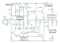
This afternoon I tried this circuit.
Obviously this is based upon the JLH class-A, but it has simultaneous class-AB output capability via the common driver transistor.
It has the same neutral sound as the original, better damping and substantial power capability for just 36W of heat.
All transistors except the input are on the heatsink. The circuit board has just ! one !transistor, but is surrounded by capacitors, including local rail 'smoothers' from a star earth. The design is stable with low impedance drive, but not tested with high Z input as I use only low Z drive.
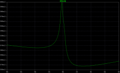
Tonight I simulated and found a flat reverse phase characteristic which suggests that any back-EMF voltage development must be in phase with the back-EMF itself, and thus the approx 55dB damping should be virtually resistive.
Unlike differential input stage amplifiers there is a power-up thump, but it is not too bad.
I still have to check out bias stabilisation, also check out current source or a driver emitter bootstrapped resistor for possible replacement of the 1k TR1 collector resistor, but my priority is not risking stability in any way that will lead to a need for capacitors or series resistors that could generate phase shifted output error from loudspeaker system generated back-EMF.
Cheers ........ Graham.
Re Post#204.
Okay, a slight slip of my fingertips !
I should have written -
An amplifier cannot be non-contributary wrt input if its damping response is not phase coherent with the back-EMF; very many high open loop gain NFB amplifiers develop quadrature error at higher (and often mid) audio frequencies. Thus the voltage development that is due to an amplifier's output impedance characteristic must be added into any amplifier/loudspeaker system analysis.
Since its publication I have liked the JLH class-A design as being one of good performance at low level.
I have also been struck by what audibly appears to be 'back-EMF neutrality' in that it it offers clean, if not substantial cone control.
However, the design lacks power, and scaling it upwards with paralleled output devices produces too much heat before decent levels of dynamic power become available.
This afternoon I tried this circuit.
Obviously this is based upon the JLH class-A, but it has simultaneous class-AB output capability via the common driver transistor.
It has the same neutral sound as the original, better damping and substantial power capability for just 36W of heat.
All transistors except the input are on the heatsink. The circuit board has just ! one !transistor, but is surrounded by capacitors, including local rail 'smoothers' from a star earth. The design is stable with low impedance drive, but not tested with high Z input as I use only low Z drive.
Tonight I simulated and found a flat reverse phase characteristic which suggests that any back-EMF voltage development must be in phase with the back-EMF itself, and thus the approx 55dB damping should be virtually resistive.
Unlike differential input stage amplifiers there is a power-up thump, but it is not too bad.
I still have to check out bias stabilisation, also check out current source or a driver emitter bootstrapped resistor for possible replacement of the 1k TR1 collector resistor, but my priority is not risking stability in any way that will lead to a need for capacitors or series resistors that could generate phase shifted output error from loudspeaker system generated back-EMF.
Cheers ........ Graham.
Attachments
Re: Re: Trying to focus the controversy
Fully agree Jan.
It came to me as a further reflection, but I had already posted. The process of learning does not end, no matter the education level and experience.
Only sometimes it is rather hard to express certain well accepted and reviewed facts when the chosen language lacks suitable constructs. What I mean in this case, is to present those facts not recurring to the tools and theory framework is not only difficult but also risks not being properly acknowledged.
Again this does not mean in any way to dismiss the posibility of fruitful exchange with people who by choice or lack thereoff, do not have the missing thechnical resources. At least for me it has been, here in this forum, a highly enriching experience.
Rodolfo
janneman said:
Rodolfo,
I agree, but I like to add that this is a gradual difference, not a principled one. In my audio life I had numurous occasions thinking: ahh, NOW I understand, only to find another layer of complexity below what I knew. Its like an onion. When you have peeled off a layer of skin, you think you see what's inside. Not so, you see .. another onion!
.....
Fully agree Jan.
It came to me as a further reflection, but I had already posted. The process of learning does not end, no matter the education level and experience.
Only sometimes it is rather hard to express certain well accepted and reviewed facts when the chosen language lacks suitable constructs. What I mean in this case, is to present those facts not recurring to the tools and theory framework is not only difficult but also risks not being properly acknowledged.
Again this does not mean in any way to dismiss the posibility of fruitful exchange with people who by choice or lack thereoff, do not have the missing thechnical resources. At least for me it has been, here in this forum, a highly enriching experience.
Rodolfo
Graham Maynard said:Hi Jan,
An amplifier cannot be non-contributary wrt input if its damping response is not phase coherent with the back-EMF....
.....very many high open loop gain NFB amplifiers develop quadrature error at higher (and often mid) audio frequencies.
Thus the voltage development that is due to an amplifier's output impedance characteristic must be added into any amplifier/loudspeaker system analysis.
It might be more illuminating if you would provide some means of demostrating the statements above.....
This is because they are at variance with all known and proven facts relating to damping factor......back EMF....etc....
Thanks in advance.
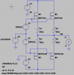
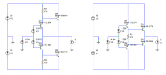
Per Greg's request, I've done some plots of the nonlinear output impedance using the IRFP240 and IRFP9240 with the source follower configuration as pictured below. The bias current was stepped from 25 mA to 150 mA in 25 mA steps. those voltages at the bottom were empirically determined to get the desired current, plus or minus a few tenths of a mA. List mode was used to step the voltages. I've expanded the current scale to +/- 8 A, because when it's shown from -20 A to +20 A, the area of discontinuity looks way squeezed together.
To be continued...
To be continued...
Attachments
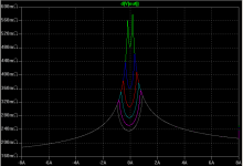
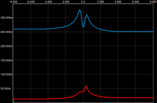
...And here is the plot. One thing to notice are the discontinuities in the resistance vs current. Are these real? I suspect not. One of my co-workers attempted to bring the SPICE level 1, 2 and 3 MOSFET models into a harmonic balance simulator. Harmonic balance simulators are useful for computing things like intermodulation distortion in the presence of sine wave inputs of many different frequencies. But they require that the transfer characteristics of the devices contain no discontinuities. If there are discontinuities, the simulator often fails to converge. He found that the SPICE MOSFET models caused convergence problems for his harmonic balance simulator due to discontinuities and had to abandon them. In short, I suspect these discontinuities are an artifact of the models and not present in real life.
Also, you can see that the performance keeps getting better as the bias current is increased. You can also see that the 9240 has lower gm than the 240 (negative current corresponds to the amp sourcing current through the N-channel device).
Also, you can see that the performance keeps getting better as the bias current is increased. You can also see that the 9240 has lower gm than the 240 (negative current corresponds to the amp sourcing current through the N-channel device).
Attachments
amplifierguru said:Can you do a BJT/MOSFET UGS CFP? Aw c'mon.
What's UGS? There's more variables with a CFP, which can cause problems with stepping. How about a schematic with values?

Hi Jorge,
What's the DC collector current of the output stage? My guess is it's pretty low?
Also, here's a thread about the JLH amp that got into a discussion of the poor accuracy of the MJL3281a models from OnSemi http://www.diyaudio.com/forums/showthread.php?postid=469394#post469394
And here's another one that shows how bad the AC parameters are http://www.diyaudio.com/forums/showthread.php?s=&threadid=20460&highlight=. I've been meaning to get around to combining the fixes for the DC and AC into one model and giving it another once over.
Something's puzzling me. Is the lack of a dip in impedance at zero output current due to an underbiased condition or does this happen as the resistance seen by the bases of the output stage increases from zero? Or an issue of different models?
"Something the leprechauns asked me when I was a sprout in Indiana has always puzzled me..."
"Something the leprechauns asked me when I was a sprout in Indiana has always puzzled me..."
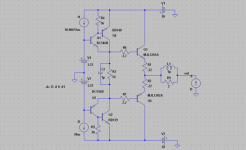
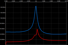
And here they are, this time with 0.22 emitter resistors, Iq still 100mA. Note the different vertical scale. Again Darlington is blue and Sziklai red.
The Sziklai shows no significant difference as the increased output impedance is reduced by the open-loop gain, whereas the Darlington's output impedance is exactly 0.22 higher. It is also now displaying the dip around zero; why doesn't that appear without emitter resistors?
The Sziklai shows no significant difference as the increased output impedance is reduced by the open-loop gain, whereas the Darlington's output impedance is exactly 0.22 higher. It is also now displaying the dip around zero; why doesn't that appear without emitter resistors?
Attachments
Mr Evil said:It is also now displaying the dip around zero; why doesn't that appear without emitter resistors?
The smaller the emitter resistors, the larger the optimum bias current. For 0.22 Ohm, Self computes 107 mA as the optimum. For 0.1 Ohm, it's about 210 mA. Go enough below optimum bias current and you get the peak at zero that doesn't dip at all. So what you had is essentially an underbias condition for the zero Ohm resistors. 100 mA is close to optimum for 0.22 Ohms, showing the dip around zero. That's why I was wondering about Jorge's bias current too.
It looks like Self's optimum bias condition also correlates with minimum variation of output impedance for a fixed EF configuration with varying bias. Makes sense - just two different ways of looking at the same thing.
In my opinion Self's bias confers to lateral and vertical Mosfets from Hitachi, Exicon, Toshiba, magnatec only......
When the game is played with IRF or APT N- channel power packs the strategy changes in meantime..... The bias issue somewhat more relates to the parameters involved in designing and obtaining the results or targetted objectives while designing power amps with output power ranging kilowatt++ levels....
The main area of consideration is the Driver stage...IRFP260 needs 2.85 volts to conduct Id=25mA @ Vds=90VDC ...but if the driver drain current is say 10mA you will definately hear cross-over at nominal output levels whereas if driver drain current is set to 50mA the cross-over simply sags to be audible at very low output level....this is because the mosfet has very huge gate capacitance and it therefore needs high driver idle current to JUMP Start the charging of gate and definately discharging it ..........
Well guys, I dont have experience in complementary mosfet amps, I only commented above in the context of n-channel Quasi complementary amps.......
Kanwar
- Status
- This old topic is closed. If you want to reopen this topic, contact a moderator using the "Report Post" button.
- Home
- Amplifiers
- Solid State
- The many faces of distortion