Wesayso,
Did you measure sensitivity of your speakers at frequencies requiring highest EQ boost?
I can't say I have due to not having a perfectly symmetrical setup. But it wasn't my goal at the time either. I cut trough the frequency response, cutting half of it and boosting the other half.
At no point I actually measured at exactly one watt or at a set voltage. To be able to get more useful data on that I'd need more room (or measure outside) neither of which is available to me at this time.
I just calibrate my separate SPL meter with REW and go from there to measuring. Keeping my eyes on the graphs.
I did try measuring at low SPL and 10 dB hotter to see if the graph would look different. I should measure at different distances to see if the 6 dB/doubling distance holds up but would need more room for that too. I don't think there would be much sense in measuring closer than the 3 meter I use now.
I'd like to compare that to 4 and 5 meter but that's not going to happen here.
Are you still in doubt of what to build? Or how to EQ (like only cut frequencies)?
Here the impedance linearization networks for left and right line array and only difference is a small change R2. Used free program XSim to model schematic program available here http://www.diyaudio.com/forums/multi-way/259865-xsim-free-crossover-designer.html.
The plots with Electrical response, Group delay, Impulse response, Step response, Square wave response is just to document the network doesn't change anything if i switch network in or out at the X Y scaling build into program. Because those five plots looks so good is because the driver model is wideband from DC-infinite HF and these plots would change alot if i had the measured response as frd file linked to the driver model S1 and then making the system a bandpass instead. The plot Watts dissipated for components is with 10watt feeded.
Interesting is small things is happening if the network is put as load in a program intended building amps and so on, for that used free from Texas Instruments TINA-TI V9. The three plots is frequency response phase and group delay. If a amp have real zero ohm impedance as shown with the voltage generator at 0 filter have no influence but see small things happen when setting amp to 50mOhm.
Will procure components then ship to Netherland and look forward get feedback.
Byrtt,
Great work here, neat to see you double checked the circuits in TINA. I use that program too and find it very helpful. You can convert T/S parameters to equivalent RLC circuit and put that as a reactive load if you wanted. I think what you demonstrate is that your RLC circuit is the mirror image of the RLC circuit that the TS parameters of the speaker system has on the response. That is a big inductor there - what is neat is all this just hangs off the positive terminal and can simply be switched on/off for easy A/B testing to hear difference.
I'd say a 250 watt into 8 ohm amplifier would be about right. Yet I still use a 100 watt amp and get by just fine in my room. I'd love to try a bigger amp. But I'm sure it would not be cheap to get a good one. My 25 year old amp has just been serviced and until I somehow get a bit of play money it will have to do.
One day I'll own a 250+ watt amp (or more than one) though .
.
Be aware, there are limits to even 25 drivers in a row. Be gentle and stay save.
One day I'll own a 250+ watt amp (or more than one) though
.Be aware, there are limits to even 25 drivers in a row. Be gentle and stay save.
She's a witch! Q and cables
Shhh- everyone "knows" cables can't make a difference - you'll be burnt at the stake if you keep talking like that (or called a subjectivist, which is worse?)
Q sensitivity can be a real problem, particularly as the TS parameters are known to change with displacement, temperature and as the drivers age.
The brute force approach is to swamp the system with a fixed impedance to drop the system Q. (olson's done this in the BTA system tweeter)
YMMV as to how it sounds
I'd expect it to be pretty darn high due to the beam forming and proximity effects - 100W should be way more that is needed for "normal" listening.
Noting that both effects above make the usual db loss over distance incorrect. What's the db/w with pink noise at the listening position ?
I'm surprised looking at the plots how much things change then. This makes me think left and right speaker needs same length cable for precision setups
Shhh- everyone "knows" cables can't make a difference - you'll be burnt at the stake if you keep talking like that (or called a subjectivist, which is worse?)
Q sensitivity can be a real problem, particularly as the TS parameters are known to change with displacement, temperature and as the drivers age.
The brute force approach is to swamp the system with a fixed impedance to drop the system Q. (olson's done this in the BTA system tweeter)
YMMV as to how it sounds
Wesayso,
Did you measure sensitivity of your speakers at frequencies requiring highest EQ boost?
I'd expect it to be pretty darn high due to the beam forming and proximity effects - 100W should be way more that is needed for "normal" listening.
Noting that both effects above make the usual db loss over distance incorrect. What's the db/w with pink noise at the listening position ?
I finally got around to testing where the dips in the right channel came from. It didn't take that long to figure it out but it will take longer to convince everyone it has to change .

Always kind of knew this had to be it, but I only got permission for these speakers if I could place them there. Kind of glad too in a way, as it is an easy fix in real life, that is, after I get permission. The rack is still hanging there though. Only tested by shielding it behind damping material.
I can't for the life of me remember where I put the original feet for this equipment more than 12 years ago. I know I had it all together in a plastic bag, seemed to recall putting it in a certain drawer. It's not there funny enough after all this time. But I'm sure once I get this solved it will be another step up in the game. Will need to re-plaster the wall in order to achieve it but hey, you've got to put in the work if you want it all!
.
Always kind of knew this had to be it, but I only got permission for these speakers if I could place them there. Kind of glad too in a way, as it is an easy fix in real life, that is, after I get permission. The rack is still hanging there though. Only tested by shielding it behind damping material.
I can't for the life of me remember where I put the original feet for this equipment more than 12 years ago. I know I had it all together in a plastic bag, seemed to recall putting it in a certain drawer. It's not there funny enough after all this time. But I'm sure once I get this solved it will be another step up in the game. Will need to re-plaster the wall in order to achieve it but hey, you've got to put in the work if you want it all!
Well done, Wesayso! It must be gratifying to have discovered that.
May I ask, what exactly is it about the rack that is causing the issue. Is it an early reflection bouncing off the equipment? Standing waves between the equipment? Rattling? Oddly enough your set-up seems balanced with the solid black box on the other side. This is an interesting find.
Bet You can not wait to hear your system with this resolved. I foresee a step up in soundstaging for sure.

.... still the same impressive subwoofer underneath the TV...
Really, it's the camera lens that schrinks my Sub and TV
It's been a little quiet around here but that doesn't mean nothing got done. I've been playing with some new templates for DRC, with a little help from gmad. So far my impressions are good, a lot easier to work with than the standard templates. Those always got me a non flat FR and needed correction afterwards.
Gmad's templates also did more fine adjustments to the frequency response than the Soft template standard version. The primary reason seems to be correction in linear phase as opposed to minimum phase for certain parts of the DRC process. A full linear phase correction right down to excess phase is giving me mixed results though.
I hope to test the impedance correction network soon to see what that brings for the line array and also have plans to change my baffle. More on that soon I hope.
...... and also have plans to change my baffle.
what improvement/modifications are you looking for with a new baffle?
It never ends, does it?
I've been enjoying the sound I have achieved so far using DRC, it's the best I've had ever, so, I'm in no hurry to tweak more, but I'm sure the bug will bite me at some point and I'll need to tinker more.
Changes to an aluminium baffle should be interesting! Not exactly easy though!
I've been enjoying the sound I have achieved so far using DRC, it's the best I've had ever, so, I'm in no hurry to tweak more, but I'm sure the bug will bite me at some point and I'll need to tinker more.
Changes to an aluminium baffle should be interesting! Not exactly easy though!
It never ends, does it?
I've been enjoying the sound I have achieved so far using DRC, it's the best I've had ever, so, I'm in no hurry to tweak more, but I'm sure the bug will bite me at some point and I'll need to tinker more.
Changes to an aluminium baffle should be interesting! Not exactly easy though!
Glad to hear you're enjoying your improved sound. And I can't say I'm disappointed with what I hear in my room, on the contrary. But one of the goals for me was to learn as much as I can, and the measurements show room for improvement. So that's what I'll try to get.
I already have aluminium as a baffle material, stiff and reasonably light. And loaded with mass loaded vinyl I made it heavier to dampen it. But between the front aluminium plate and the actual baffle I have mass loaded vinyl and neoprene. The neoprene acts as an isolator between both layers if I have to guess. Not what I wanted. I wanted the double aluminium baffle to act as a constrained layer. So I'm going to experiment with using butyl between both aluminium layers. It will be much more messy if I ever have to take them apart again but I'll have to live with that when the time comes. The only thing I'm not sure off right now is changing the neoprene to butyl between baffle and enclosure too. Right now the neoprene there does a good job to isolate the baffle from the enclosure. But it also means less of the enclosure weight is used as a counter force for the moving cones. I'm operating today so I'll let you know what I decide later on
.Well I operated one array and replaced the mass loaded vinyl and neoprene with butyl. But only between the aluminium baffles. Didn't have time to run any measurements yet apart from an impedance test. I had a hard time cleaning up the front baffle and had to re-polish after glue residue removal. The impedance plot changed a bit, lowering the peak value from 12.2 ohm to 11.7. Had a look at XSim to see if it changed the proposed correction network. It was still quite valid but I could re-tune it to do a little better. BYRTT, are you out there? Changing the inductor (L1) to 14.5 mH and the resistor (R2) to 15.5 Ohm gave the new best flat result.
Revisiting this topic I'm still wondering what a series resistor would do to the graphs posted. I've been looking at the XSim simulation and added the series resistor, for example an 8.2 Ohm resistor, further nulls out the impedance bumps and smooth's the phase even further. At the cost of about 3 dB of max output.
Just wondering about the effects here as with an impedance correction and a series resistor one would seem to turn a solid state amplifier into a current source.
See this interesting read from Nelson Pass:
http://www.firstwatt.com/pdf/art_cs_amps.pdf
Think this gets pretty exiting thanks the data you support in post 1156/1157 because as you say below we probably just look for very small tweaks to go from good to great particular for your system. Others may think we go in too small shoes here but if that network end up being a improvement then at same seems we can document data parameters that change in the system adding the corrections and that's a force that can lead to logic too for us measurement data believers.
Ofcourse i could hope the network will repair all of the group delay resonance shown in post 1156 but fear it seems be too many mSec repair needed there, and a speculation is if this behavour is maybe why many recommend a drivers passband is preferred to be XO higher in frequency than its resonance or it could be the downside of the lines length you have mentioned before, but lets see how much the network change that resonance in real world.
Regarding output impedance your amp wonder is damping factor 70 or 200, gives 114 or 40 mOhm output impedance into 8ohm loads. See attached data my amp funny how close our respective amps are at specs and that i used 50mOhm for the amp sim was influenced by own amp data.
Attach some new amp plots based on 40 and 114mOhm output impedance and with the 114mOhm output impedance one added four steps of speaker cable resistance. Personal i prefer and use cat5 or 6 solid cable for speakers in lengths up to 4 meters. Such cable typical add 100mOhm resistance each meter and I'm surprised looking at the plots how much things change then. This makes me think left and right speaker needs same length cable for precision setups and wonder if right line array have shorter speaker cable in its placed much closer to amp. In i have two physic stereo AU-D9 amps think i will try move one out to each speaker with short 1 meter cable and see what happens to sound. Regarding adding R to sim speakercable i could very well add L and C but lets take that later I'm not pro this stuff so it takes me quite some time. Could even go further and with my DATS device measure both RLC real world for my speaker cables.
Revisiting this topic I'm still wondering what a series resistor would do to the graphs posted. I've been looking at the XSim simulation and added the series resistor, for example an 8.2 Ohm resistor, further nulls out the impedance bumps and smooth's the phase even further. At the cost of about 3 dB of max output.
Just wondering about the effects here as with an impedance correction and a series resistor one would seem to turn a solid state amplifier into a current source.
See this interesting read from Nelson Pass:
http://www.firstwatt.com/pdf/art_cs_amps.pdf
Last edited:
Little by little I'm closing in on the eyebrows... Today I did nothing but listen to music after a little experiment I did yesterday.
A bit of background... Halair has build a similar line array and published the REW measurements in order to get some help on / move ahead with EQ. I saved those measurements to have some kind of reference to my own setup. I look for trends that are related to the specific type of speaker and that way try to filter out the things that are room related and other things that are speaker related.
As I am deeply into the believe phase is a very important factor to achieve realism I look at the phase behaviour in the early wave front. So I spend a lot of time on the REW graphs gating the measurements and seeing what it does with the phase plot. So I did that on Halair's REW file as well. Something strange popped up.
His Right side measurement was showing very clean phase behaviour up until about 5 ms in the high frequencies. The left one wasn't this clean at all. Mine weren't clean, showing phase wraps as early as 0.9 ms. I immediately looked for a picture I knew he posted showing his room. The right speaker is closest to the side wall so I didn't get why that speaker could have clean phase behaviour to 5 ms compared to the free standing left speaker.
Here's the picture of his room (hope it's alright to post it)
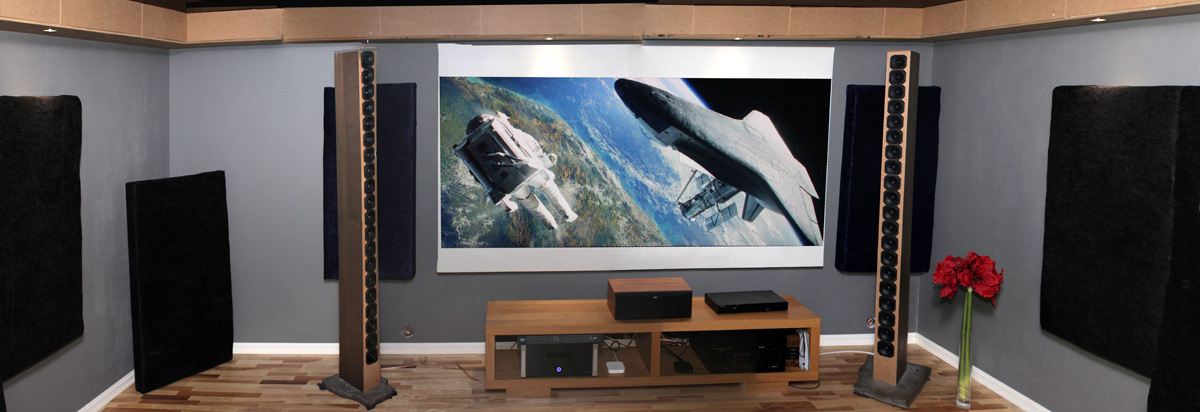
Do you guys notice the difference? I immediately PM-ed Halair to confirm...
Yes, the difference is the wire running to the speaker. The left one is connected with generic multi strand wire while the right one is connected with double solid core wire (4 cores total).
So on to a little experiment of my own. I gathered all kinds of wires to test this out. I even used solid core copper wire, normally used in my house for wiring my outputs...
Here's a frequency plot with my old wires, thick multi strand wire, 24 years old, restriped of coarse...

note this is the result after convolution, generated minimum phase included as a reference
After a few tests I went back in my garage and found some fairly new wire in my stash, I got it while buying a second hand Genesis Car audio amplifier. The seller included it in the package. It's looking much like generic wire with the difference that the core wires are very stiff. This performed very much like the solid core house electrical wire also tested. The result:

Both plots are smoothed 1/12, gated at 5 ms and convoluted after a basic measurement
The acoustical phase being flat compared to the minimum phase is part of the FIR correction
No change in the position of the array between these plots. I always thought the phase wraps were caused by reflections or diffraction.
Glad I had that reference from Halair available or I wouldn't have found out about this. Makes me more confident the impedance compensation of the entire speaker could bring along further improvements.
Interesting huh? Too bad I couldn't find any Cat5 or 6 to test in my house. I should have it somewhere.
A bit of background... Halair has build a similar line array and published the REW measurements in order to get some help on / move ahead with EQ. I saved those measurements to have some kind of reference to my own setup. I look for trends that are related to the specific type of speaker and that way try to filter out the things that are room related and other things that are speaker related.
As I am deeply into the believe phase is a very important factor to achieve realism I look at the phase behaviour in the early wave front. So I spend a lot of time on the REW graphs gating the measurements and seeing what it does with the phase plot. So I did that on Halair's REW file as well. Something strange popped up.
His Right side measurement was showing very clean phase behaviour up until about 5 ms in the high frequencies. The left one wasn't this clean at all. Mine weren't clean, showing phase wraps as early as 0.9 ms. I immediately looked for a picture I knew he posted showing his room. The right speaker is closest to the side wall so I didn't get why that speaker could have clean phase behaviour to 5 ms compared to the free standing left speaker.
Here's the picture of his room (hope it's alright to post it
)
Do you guys notice the difference? I immediately PM-ed Halair to confirm...
Yes, the difference is the wire running to the speaker. The left one is connected with generic multi strand wire while the right one is connected with double solid core wire (4 cores total).
So on to a little experiment of my own. I gathered all kinds of wires to test this out. I even used solid core copper wire, normally used in my house for wiring my outputs...
Here's a frequency plot with my old wires, thick multi strand wire, 24 years old, restriped of coarse...
note this is the result after convolution, generated minimum phase included as a reference
After a few tests I went back in my garage and found some fairly new wire in my stash, I got it while buying a second hand Genesis Car audio amplifier. The seller included it in the package. It's looking much like generic wire with the difference that the core wires are very stiff. This performed very much like the solid core house electrical wire also tested. The result:
Both plots are smoothed 1/12, gated at 5 ms and convoluted after a basic measurement
The acoustical phase being flat compared to the minimum phase is part of the FIR correction
No change in the position of the array between these plots. I always thought the phase wraps were caused by reflections or diffraction.
Glad I had that reference from Halair available or I wouldn't have found out about this. Makes me more confident the impedance compensation of the entire speaker could bring along further improvements.
Interesting huh? Too bad I couldn't find any Cat5 or 6 to test in my house. I should have it somewhere.
Last edited:
Glad I am reading this. Heck, this is the FIRST time I have seen quantifiable proof that solid core vs stranded core makes a difference!!! Bravo! Is it a real effect? Do you get phase wraps if you switch back?
It's all very serendipitous. I was testing my 10F/RS225 FAST reference monitors last night with the new TDA7492 amp. I noticed a phase wrap at 2kHz on the left speaker. But not on the right. They have same wiring (even internally solid core cat5 24ga single strand on the 10F and multi stranded copper glad aluminum core cheap 18 ga hookup clear insulation zip wire). One of the amps runs hotter than the other. The hot one has no phase wrap. I could not figure it out. Thing to try is swap speaker positions and see if phase wrap follows speaker or is it amp/wiring related?
The wrap was not there with 3116 amp so I am suspecting that it has a significant effect - the impedance and damping of the amp on the whole system.
Being an IT guy, I am surprised you don't have a Cat5 patch cable in your house somewhere to cannibalize for the test.
Last edited:
Amazing isn't it? Me not having Cat5 wires anywhere in the house . I know I have it, but I do have a girlfriend that's very good at hiding things from me. Yeah I'm sloppy and chaotic and leave everything around me, making a mess. But that's how I lose things around here... my own fault I guess .
The difference is real. I swapped cables in and out to test. I even made combinations by paralleling cables. Phase wraps can be a result of many things, but I want the phase as clean as possible in that first wave front. That's why I spend quite a bit of time going over my REW plots to find clues.
Is your phase wrap there even when gated for a very short time? I click trough the gating from 0.5 ms to about 20 ms just to observe that behaviour and try to link it to reflections and other possible causes. A little blimp on the impedance curve could cause it even.
I'm thinking arrays exaggerate these tiny differences due to being large. The sound from the outer drivers is going to take longer to reach the mic than the middle one.
It should be simpler to get it under control with a single speaker.
. I know I have it, but I do have a girlfriend that's very good at hiding things from me. Yeah I'm sloppy and chaotic and leave everything around me, making a mess. But that's how I lose things around here... my own fault I guess .The difference is real. I swapped cables in and out to test. I even made combinations by paralleling cables. Phase wraps can be a result of many things, but I want the phase as clean as possible in that first wave front. That's why I spend quite a bit of time going over my REW plots to find clues.
Is your phase wrap there even when gated for a very short time? I click trough the gating from 0.5 ms to about 20 ms just to observe that behaviour and try to link it to reflections and other possible causes. A little blimp on the impedance curve could cause it even.
I'm thinking arrays exaggerate these tiny differences due to being large. The sound from the outer drivers is going to take longer to reach the mic than the middle one.
It should be simpler to get it under control with a single speaker.
- Home
- Loudspeakers
- Full Range
- The making of: The Two Towers (a 25 driver Full Range line array)