You might block sand down past the corrosion, because if it's too deep, bead blasting will only leave a crater or valley in how it will look and then what ?
Block sand then either bead blast for a frosted look or sand blast for a real ugly finish that will beg for painting it over..,.
Or block it down, then finish with scotch bright pads in a direction you like
Followed up with a Aluminium prep acid wash.
Now your closer back to how it was originally.
Finish up with a clear gloss lacquer.
Regards
David
I think that particular deck is going to need to be painted, I don't see how after sandblasting there is not going to be significant material removed. I would use automotive body filler in the damaged areas and treat the whole chassis top to a really good paint job. Unfortunate, but done right it will look great..
The better of the two will probably be good with your proposed refinish.
Can't wait to see what SY does with these tables, and at some point maybe I will make it to Chicago to see for myself how they turned out.. LOL
The better of the two will probably be good with your proposed refinish.
Can't wait to see what SY does with these tables, and at some point maybe I will make it to Chicago to see for myself how they turned out.. LOL
I may get a bit fancier than that since I can custom formulate and source materials for just about any kind or method of coating and filling. I have a goofy idea that I'm going to prototype. The next big challenge will be figuring out how to wheedle some time on a big lathe so I can make molds for a new mat.
Just as a thought, I have done some experimenting with different grits on a random orbital sander on aluminum.
80grit is a bit too textured for my liking, 120grit is about where I like it, 400grit is what i use if I will be making brushed aluminum finish afterward, it leaves a very fine "Angel Hair" pattern in the metal.
80grit is a bit too textured for my liking, 120grit is about where I like it, 400grit is what i use if I will be making brushed aluminum finish afterward, it leaves a very fine "Angel Hair" pattern in the metal.
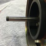
I did some work on the bearing of mine last night.
I don't believe that the motor on mine has ever been open, as the glue holding the rubber covers over the two screws of the retaining tab look original, and after I bought it I was told it had been in the studio it was pulled out of its entire life.
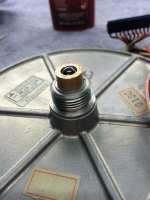
The shaft was nicely oiled save the oil at the bottom by the thrust bearing which had turned in to a light grease. Shaft wear to looks to be minimal.
Now, I noticed a few things...
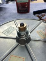
First, the bearing cap has a dimple where the ball sits. I've read that others believe this is due to the ball spinning during operation, but I don't believe that to be the case. On mine the ball sits rather snugly in the bushing, snugly enough that there's no way it can spin. If it were spinning, the damage to the cap would be far greater as the cap material is very soft, and there's no evidence of any lubrication in the cap.
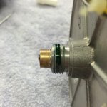
Second, there was very light abrasions to the tops of the motor coils. The thrust pad was in good shape, and there was no sign that this was caused by the top-hat rubbing the coils due to thrust pad wear or any other issue.
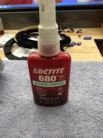
Third, the 'thread lock' on the bearing doesn't look to be thread lock to me. It's green in color, and judging by the amount of heat it took to free it, I believe it's Loctite 680 retaining compound, or something very similar. BTW, if you heat it up enough you can unscrew it with a towel and your hand as retaining compound becomes very fluid under appropriate heat. I had to stop and heat mine twice to keep it fluid, but no tools were necessary.
Now, my first attempt at putting it back together I put the cap back on, threw a few drops of oil in and put the top-hat back on. My bearing is so tight that after 30 minutes with light pressure, it hadn't settled at all.
In mass production having process that take exorbitant amounts of time to complete, having variables, or having situations where line workers have to interpret information and make decisions is simply not done. Therefore, I feel the more reasonable explanation for the 'wear' seen on the parts is simply due to how it was assembled:
1) The top-hat is placed in the bearing with the ball and cap absent. The magnet holds it snug against the motor coils, so movement and potential damage to the coils are minimized.
2) The motor is inverted, and 2-3 drops of oil are placed in the bottom of the bearing.
3) The ball bearing is placed at the opening of the bushing.
4) Retaining compound is generously applied to the threads, and the cap is threaded on and tightened hand-snug.
That's it. The entire process takes a minute or two, explains all the witness marks on the parts, puts the ball bearing at the right depth in the bushing, assures proper lubrication at the bottom of the bearing and thrust bearing, and you don't have to let parts settle for hours, hoping all the air was displaced.
Just my .02.
I don't believe that the motor on mine has ever been open, as the glue holding the rubber covers over the two screws of the retaining tab look original, and after I bought it I was told it had been in the studio it was pulled out of its entire life.
The shaft was nicely oiled save the oil at the bottom by the thrust bearing which had turned in to a light grease. Shaft wear to looks to be minimal.
Now, I noticed a few things...
First, the bearing cap has a dimple where the ball sits. I've read that others believe this is due to the ball spinning during operation, but I don't believe that to be the case. On mine the ball sits rather snugly in the bushing, snugly enough that there's no way it can spin. If it were spinning, the damage to the cap would be far greater as the cap material is very soft, and there's no evidence of any lubrication in the cap.
Second, there was very light abrasions to the tops of the motor coils. The thrust pad was in good shape, and there was no sign that this was caused by the top-hat rubbing the coils due to thrust pad wear or any other issue.
Third, the 'thread lock' on the bearing doesn't look to be thread lock to me. It's green in color, and judging by the amount of heat it took to free it, I believe it's Loctite 680 retaining compound, or something very similar. BTW, if you heat it up enough you can unscrew it with a towel and your hand as retaining compound becomes very fluid under appropriate heat. I had to stop and heat mine twice to keep it fluid, but no tools were necessary.
Now, my first attempt at putting it back together I put the cap back on, threw a few drops of oil in and put the top-hat back on. My bearing is so tight that after 30 minutes with light pressure, it hadn't settled at all.
In mass production having process that take exorbitant amounts of time to complete, having variables, or having situations where line workers have to interpret information and make decisions is simply not done. Therefore, I feel the more reasonable explanation for the 'wear' seen on the parts is simply due to how it was assembled:
1) The top-hat is placed in the bearing with the ball and cap absent. The magnet holds it snug against the motor coils, so movement and potential damage to the coils are minimized.
2) The motor is inverted, and 2-3 drops of oil are placed in the bottom of the bearing.
3) The ball bearing is placed at the opening of the bushing.
4) Retaining compound is generously applied to the threads, and the cap is threaded on and tightened hand-snug.
That's it. The entire process takes a minute or two, explains all the witness marks on the parts, puts the ball bearing at the right depth in the bushing, assures proper lubrication at the bottom of the bearing and thrust bearing, and you don't have to let parts settle for hours, hoping all the air was displaced.
Just my .02.
Attachments
Yes, just a hot air gun. I would've used my hot air rework station for better control of the heat, but I lent it to a buddy who's knock-off Hakko couldn't cut it for some BGA rework he was doing.
Even with the cap too hot to touch, the motor casing itself was barely warm. No problems.
Even with the cap too hot to touch, the motor casing itself was barely warm. No problems.
I may get a bit fancier than that since I can custom formulate and source materials for just about any kind or method of coating and filling. I have a goofy idea that I'm going to prototype. The next big challenge will be figuring out how to wheedle some time on a big lathe so I can make molds for a new mat.
No sandblasting, fine miling first.
I don't know much about their history except that they had been carefully stored when I got them. My suspicion is that the more corroded chassis of the two got wet and stayed wet for some longish period of time
Wrapping metallic assemblies with plastic for storage is a bad practice.
Moisture is entrapped by the plastic cover, promoting electrochemical corrosion on the metals ( crevice corrosion).
With aluminum alloys, the result is deep pittings or flaking (integranular corrosion) depending on how the material was formed.
If it is necessary to wrap the assy with plastic, include moisture absorbing crystals in refill packs, renewing them when required.
It is good that the wounded animal found a good home
")
George
No affiliation to the seller but saw this on net so thought it would be of interest to someone. Fromthe other stuff on sale looks like a recording studio sale.
Technics SP10 MK2 Turntable x 5 and 7 Power Supplies | eBay
The seller has not mentioned if they are working or not.
Regards.
Technics SP10 MK2 Turntable x 5 and 7 Power Supplies | eBay
The seller has not mentioned if they are working or not.
Regards.
Yes, I saw those. It's an interesting listing...
He's not saying anything about condition nor operational status;
He's selling as a mis-matched lot;
It's local pickup only;
And for that he's asking complete top-dollar, the price you would expect for a un-restored deck in good operational and cosmetic condition...
Good luck.
He's not saying anything about condition nor operational status;
He's selling as a mis-matched lot;
It's local pickup only;
And for that he's asking complete top-dollar, the price you would expect for a un-restored deck in good operational and cosmetic condition...
Good luck.
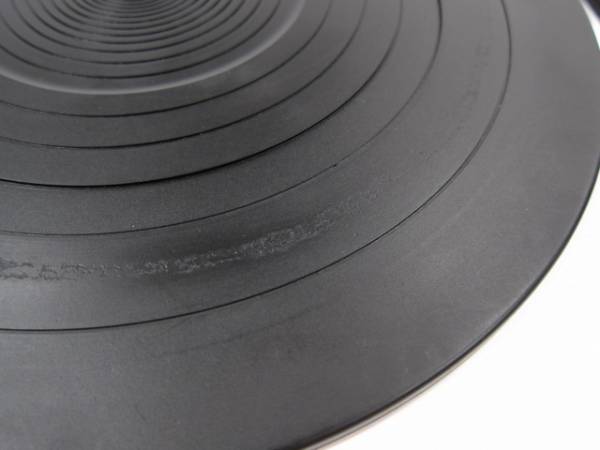
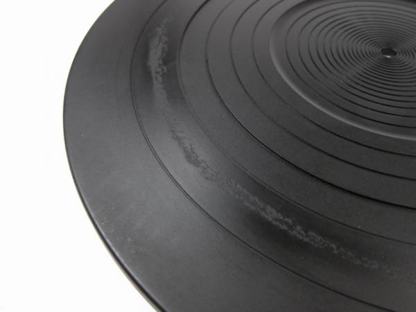
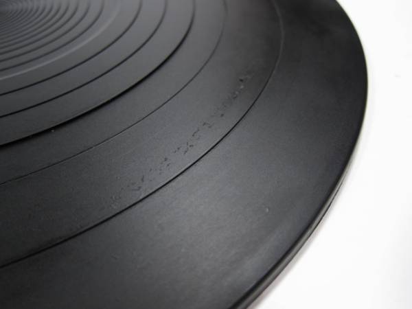
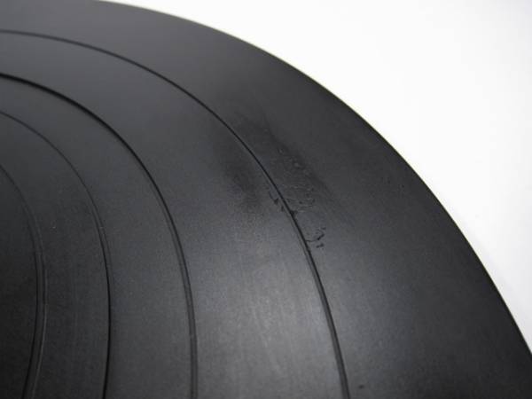
Platter Mat -
Taking the advice of very warm water, a bit of detergent and letting it soak, the glue residue is almost entirely removed. There is still some damage to the rubber itself, but it's almost all cosmetic.
The two mats are photographed to show the damage. In general, they look pretty nice.
Taking the advice of very warm water, a bit of detergent and letting it soak, the glue residue is almost entirely removed. There is still some damage to the rubber itself, but it's almost all cosmetic.
The two mats are photographed to show the damage. In general, they look pretty nice.
PSU -
Here's an interesting story, sorry no photos, and this is probably the most eye-opening thing about this project thus far;
The PSU requirements are fairly benign - there are 3 voltages, all with a common ground,
5V (15mA) This is the logic supply
32.5V (250mA) Motor supply
140V (7mA) To light (but not control) the strobe
Now looking at that you see nothing at all out of the ordinary - and to get things to work, the strobe doesn't need to light up.
SO... why not hook it up to a two-channel regulated bench supply? One output at 5V, one at 32.5V. Easy.
Well, not so much... With three different supplies, a linear HP, a big switcher chinese thing, and a big linear Lambda, all three PSU were not able to drive the motor. It must be too inductive a load or something similar. The HP made the speed just run away, the lambda it ran fast, and the switcher was just massively confused as it was trying to relay through whatever voltage it though it was supposed to supply, at which time I unplugged the table.
These results were identical for both of my tables.
Both tables run fine on the Technics supply.
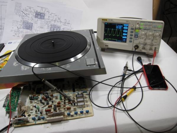
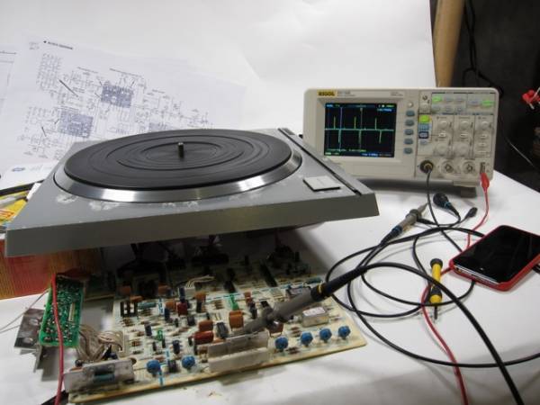
Testing -
So the general setup for testing is as follows,
1) Remove PCB screws and a few other assemblies from the position under the chassis,
2) prop table up, let PCB onto tabletop,
3) get service manual (on computer) and schematics at hand,
4) have at it.
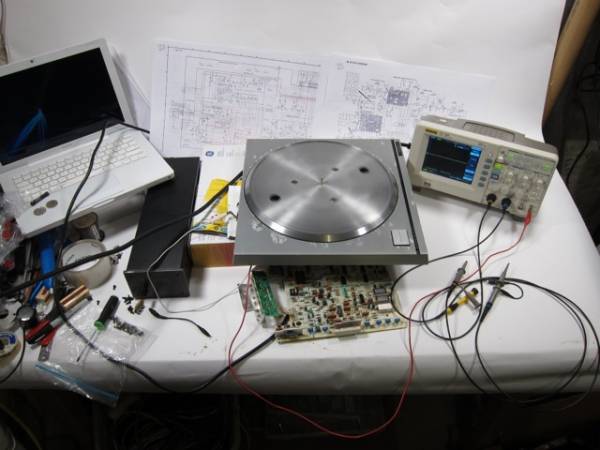
At this point all I am am doing is comparing waveforms and parameters from the schematic to what I measure in real life. So far this looks rock solid.
Some random photos -
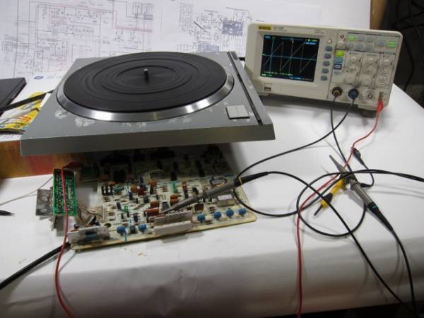
33RPM drive speed good
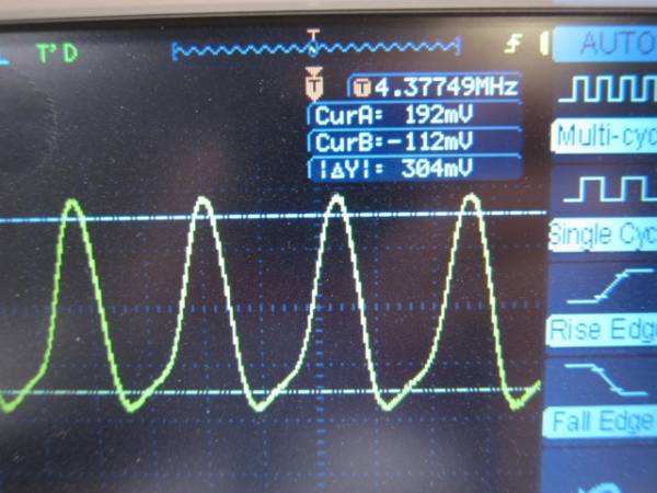
Quarts crystal frequency is exactly what it's supposed to be
So the general setup for testing is as follows,
1) Remove PCB screws and a few other assemblies from the position under the chassis,
2) prop table up, let PCB onto tabletop,
3) get service manual (on computer) and schematics at hand,
4) have at it.
At this point all I am am doing is comparing waveforms and parameters from the schematic to what I measure in real life. So far this looks rock solid.
Some random photos -
33RPM drive speed good
Quarts crystal frequency is exactly what it's supposed to be
Both tables run fine on the Technics supply.
Was that both before and after you changed all the capacitors ?
If so I would suspect your bench PSU's.
Dave
- Home
- Source & Line
- Analogue Source
- The Incredible Technics SP-10 Thread