They're pretty readily available from most tube vendors. The EF86 in particular is a common tube in guitar amps and is currently produced by JJ and Electro-Harmonix, although opinions vary on their quality compared to NOS examples. The 6CW4 appears to be available from all the vendors I've checked for around $17
Looking for a bunch of EF86 tubes and 6CW4. ??
Thx-RNMarsh
Go for 6J32P (Soviet equivalent). Cheap and plentiful on ebay or other sites.
6AF11 revisited
About 2 years ago, I put together a 6AF11 amp based on the Squirrel Monkey idea. I was able to stabilize it with no oscillation, and it sounded good.
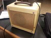
I wanted to see if I could easily replicate the stable circuit to make sure it was not just the original layout or some other fluke that made it not oscillate. The answer is yes. No oscillation at any volume or settings. At about half volume, it is clean and chimey. Full on it has pretty good drive and nice distortion. In pentode it is around 1 watt based on rough measurements, just hitting a power chord and measuring the RMS volts on the speaker terminals.
Sounds surprisingly good for a $3 TV tube. The only tone control is a bright switch. Enabling the feedback calms the bite down a little bit.
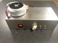
The speaker is the Eminence 8" 820H Patriot. Nice sounding speaker for an 8".
Scott
About 2 years ago, I put together a 6AF11 amp based on the Squirrel Monkey idea. I was able to stabilize it with no oscillation, and it sounded good.
I wanted to see if I could easily replicate the stable circuit to make sure it was not just the original layout or some other fluke that made it not oscillate. The answer is yes. No oscillation at any volume or settings. At about half volume, it is clean and chimey. Full on it has pretty good drive and nice distortion. In pentode it is around 1 watt based on rough measurements, just hitting a power chord and measuring the RMS volts on the speaker terminals.
Sounds surprisingly good for a $3 TV tube. The only tone control is a bright switch. Enabling the feedback calms the bite down a little bit.
The speaker is the Eminence 8" 820H Patriot. Nice sounding speaker for an 8".
Scott
Attachments
Thanks.
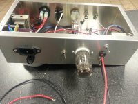
A hybrid star/buss ground. On the turret board there are 2 groups of ground points. I connected a solid copper bare 18AWG wire between the pentode & second stage cathode circuit grounds and the 1st stage cathode circuit ground. All other grounds: enclosure, power supply, volume control, input jack, OT secondary, and heater ground connect to this buss wire. The AC ground is a separate wire grounded to the enclosure right at the IEC power inlet.
Concerning the heater ground, I did not use the conventional artificial center tap method, I just grounded one side of the heater supply. It does make a difference in this case which side is grounded. One side gets rid of the hum, and the other side does not have as much of an effect.
Last edited:
Speco T-7010 trivia.
I got some of these years ago before they were redesigned. I recently had access to a fancy RLC analyzer and took a bunch of measurements on one.
This may be useless info since you can't buy the old design, but hopefully somebody else has some hoarded away.
I converted an XLSX spreadsheet to PDF because I don't have any spreadsheet s/w on this PC, and it's viewable.
I hope it's mostly self-explanatory...I measured inductances for various windings at 1 kHz 1 Vrms, then 10 Vrms and multiple frequencies, leakage inductance for various measured and shorted windings, and whatever else seemed interesting at the time, before I lost my opportunity...visiting someone with work access to a lab...
All inductance measurements were 'dry' (no DC).
I hope this of interesting if not useful to somebody. I found it interesting to see how much primary inductance it had under different measurement conditions. 10 V was the maximum available so that's as high as the data went.
The lamination stack approximate measurements were made by offsetting the stamped steel frame thickness or double that as appropriate with a digital caliper. The cryptic EI lamination dimensions refer to the E and I lamination shapes, and the 'E c w' is E lam center leg width. 'E t/b w' is the width of the other two legs of the E shape lamination.
I didn't figure out the core area, but that's probably easy to figure out, despite being of little use in this case ;O).
Attachments
Last edited:
bst offered major contributors to this thread a package of electronic components and mine included 12AB5 power pentodes (12V 9-pin 6V6 equivalent). I used a couple in an amp I am just finishing up. I guess it is fitting to include it here as it was built with the same idea in mind. How could you put together an inexpensive tube amp. In this case it is not bound by the $100 limit although a thrifty person could come close.
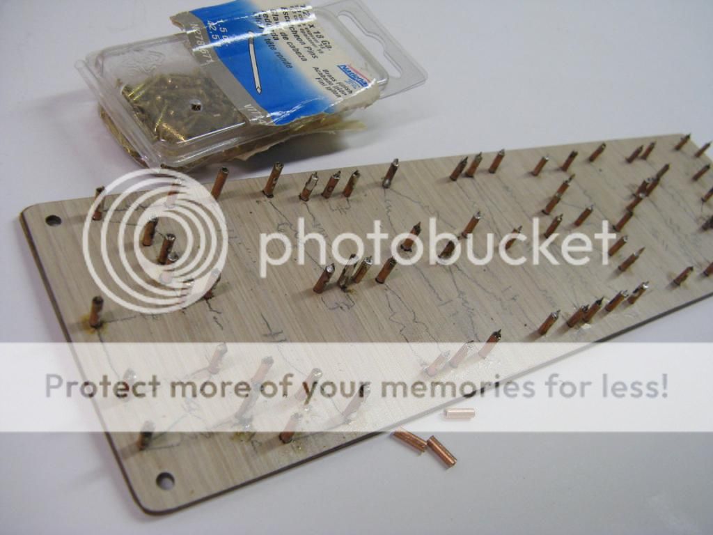
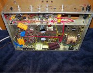
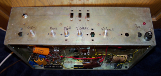
The chassis was an old one that I used in my attempt at making a 100W amp in my younger years. Trimmed it and bent it in my vice with a couple pieces of wood to hold the metal. Not pretty but does the job. For the board I used leftover pieces of counter top laminate glued together with epoxy, Brass finished nails and a piece of copper hobby tubing as my turrets.
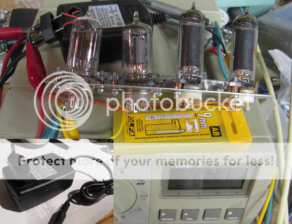
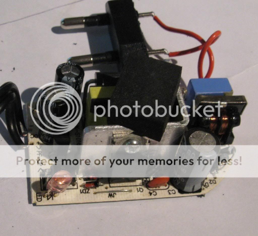
I used a 12V adapter bought online for about $5. Checked out whether I would have enough voltage, looked like I did.
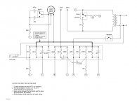
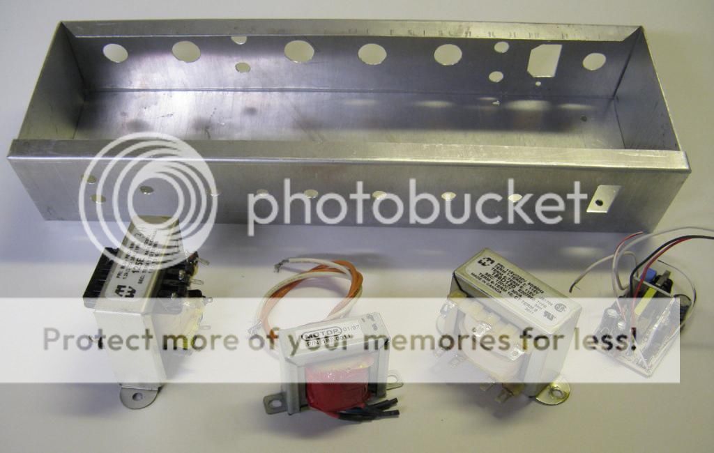
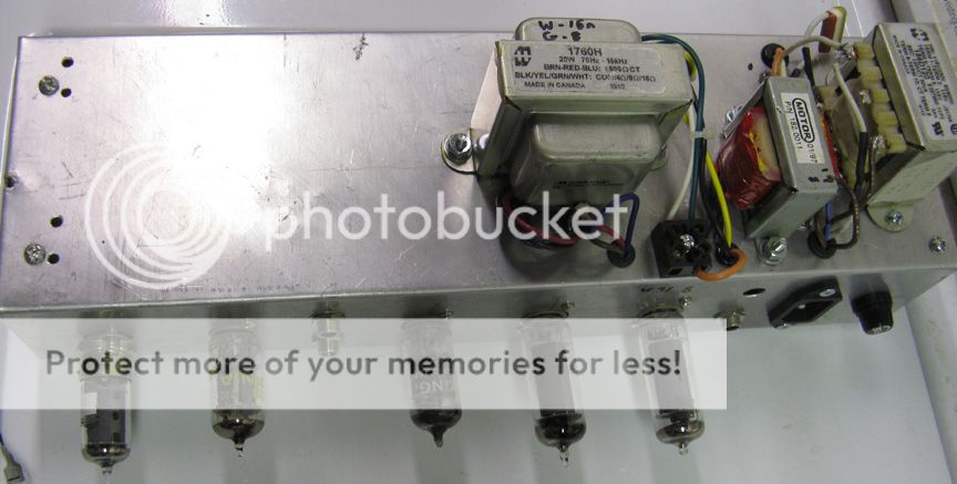
Used a 20W 1760H Hammond output transformer, the major cost in the build at $40. Also a 120V/240V to 120V isolation transformer as the power transformer which was about $14. I fed the power into the secondary and used the 240V winding arangment to get out 208V which I then fed to a voltage doubler. The dc voltage goes a little over 500V so you need your electrolytics to be rated for it. Originally I used the transformer with the 120V coming into the regular line windings but only got around 320V when running the amp. The capacitors I had were scrounged out of dead electronic lighting ballasts which had a 350V rating.
When I decided to up the voltage I had to rearrange the parts and fit an extra set of capacitors in series with balancing resistors. The doubler capacitors were scrounged out of old computer power supplies along with the power cord socket. The 'choke' was a 12V transformer that I cut the secondary wires off and used the primary winding as the choke. Another found zero cost item. It had around the right inductance and it seems to work. Originally I was going to use the 125A Hammond transformer but went with the 6.6k primary one.
The circuit running the 320V. Not much excess room. Originally I was going to go cathode biased but changed to fixed bias after laying out part of the board. I also added a post inverter master volume rather than one before the PI, would have laid out the board differently if I thought of it originally.
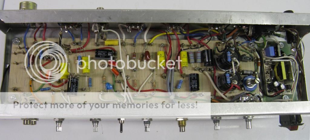
Of course when I went with the higher voltage and somehow get the other parts in the empty spaces with the 'turrets' that were in place. Would never lay out a board in this way otherwise. Had a mosfet 'cathode follower' on the input pentode, ended up taking it out. Still adjusting the power supply voltages here by swapping out resistors.
With a Fender 12" out of a pro Jr (I think) I got for $30 used the total with a pine cabinet using laminated pine shelving a 5E3 sized cabinet will get me around the 30 lb mark. I was also thinking of using a 10" WGS speaker for around a 25 lb combo.
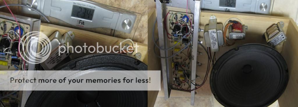
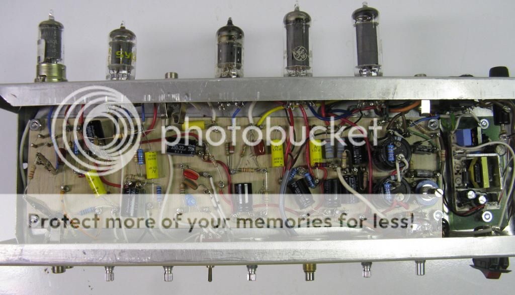
Just finishing up the cabinet right now. The amp with the Fender speaker will do about 115 dB at 1M more or less clean and does not get much louder dirty. I need to update the schematic values I used. Basically it is a 12AU6 pentode up front, a 12AX7 gain stage with cathode follower, LTP PI, and the 12AB5's. Sorry for the long post.
The chassis was an old one that I used in my attempt at making a 100W amp in my younger years. Trimmed it and bent it in my vice with a couple pieces of wood to hold the metal. Not pretty but does the job. For the board I used leftover pieces of counter top laminate glued together with epoxy, Brass finished nails and a piece of copper hobby tubing as my turrets.
I used a 12V adapter bought online for about $5. Checked out whether I would have enough voltage, looked like I did.
Used a 20W 1760H Hammond output transformer, the major cost in the build at $40. Also a 120V/240V to 120V isolation transformer as the power transformer which was about $14. I fed the power into the secondary and used the 240V winding arangment to get out 208V which I then fed to a voltage doubler. The dc voltage goes a little over 500V so you need your electrolytics to be rated for it. Originally I used the transformer with the 120V coming into the regular line windings but only got around 320V when running the amp. The capacitors I had were scrounged out of dead electronic lighting ballasts which had a 350V rating.
When I decided to up the voltage I had to rearrange the parts and fit an extra set of capacitors in series with balancing resistors. The doubler capacitors were scrounged out of old computer power supplies along with the power cord socket. The 'choke' was a 12V transformer that I cut the secondary wires off and used the primary winding as the choke. Another found zero cost item. It had around the right inductance and it seems to work. Originally I was going to use the 125A Hammond transformer but went with the 6.6k primary one.
The circuit running the 320V. Not much excess room. Originally I was going to go cathode biased but changed to fixed bias after laying out part of the board. I also added a post inverter master volume rather than one before the PI, would have laid out the board differently if I thought of it originally.
Of course when I went with the higher voltage and somehow get the other parts in the empty spaces with the 'turrets' that were in place. Would never lay out a board in this way otherwise. Had a mosfet 'cathode follower' on the input pentode, ended up taking it out. Still adjusting the power supply voltages here by swapping out resistors.
With a Fender 12" out of a pro Jr (I think) I got for $30 used the total with a pine cabinet using laminated pine shelving a 5E3 sized cabinet will get me around the 30 lb mark. I was also thinking of using a 10" WGS speaker for around a 25 lb combo.
Just finishing up the cabinet right now. The amp with the Fender speaker will do about 115 dB at 1M more or less clean and does not get much louder dirty. I need to update the schematic values I used. Basically it is a 12AU6 pentode up front, a 12AX7 gain stage with cathode follower, LTP PI, and the 12AB5's. Sorry for the long post.
That's a great project. The amp looks really good. You certainly took "resourceful" to it's full meaning.
So that's a little switcher for the tube filaments? Any issues with noise?
Were you going to post the schematic?
I have to do some measurements to see what values I used and update the schematic, shortly. Other than the pentode up front has a little more hiss than if I used a triode this is a very quiet amp. No hum, I did the headphone trick to find a low hum spot on the chassis for the OT, 80 uF of capacitance on the OT node, the 'choke' seems to work. If it were not for the preamp volume turned up all the way giving some hiss you would be hard pressed to know the amp is on. I am very happy with it.
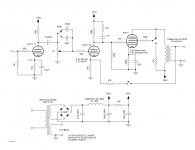
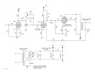
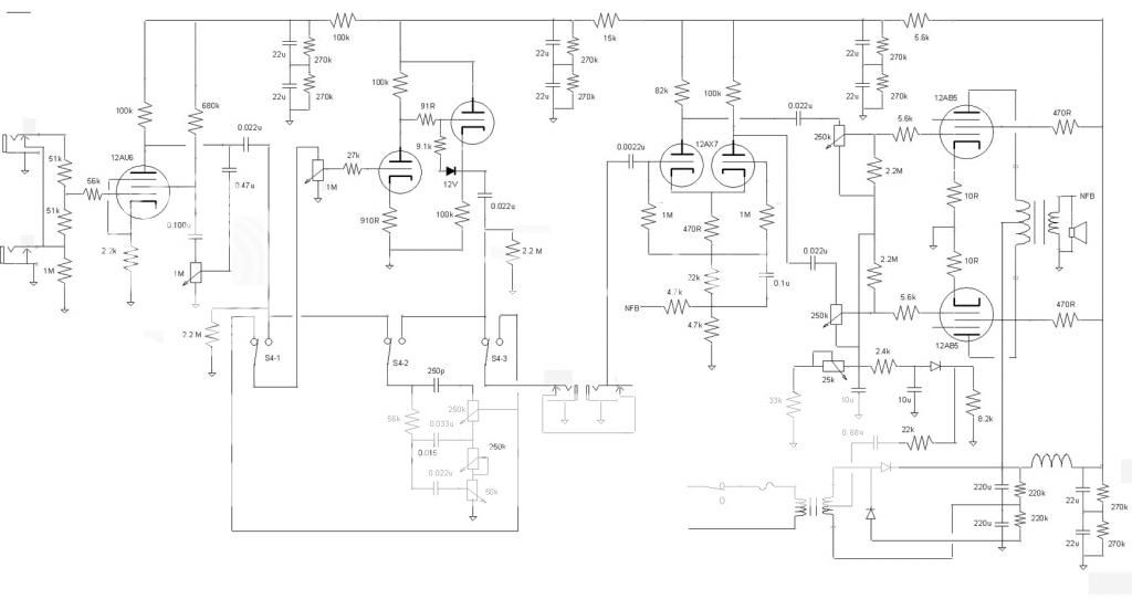
Thanks gibs. Some of what I learned during the challenge made it into the making of this amp. I could have done things a lot easier, buying bits and pieces but I wanted to show there are other ways to do things when you are short of cash. Here is the schematic. The nice thing is the 12AB5 tubes can be had for about $5 each, the 12AU6 also, the two 12AX7's I used as I had them but the dual triode's out of Russia are another way to go shaving a few bucks.
The fixed bias supply is a little more involved than usual as I was using a bridge rectifier and the 0.68 uF cap was needed to isolate the dc, the 22k and 8.2k resistors were needed to get the right range. Since I used two 120V windings in series for the secondary there was no reason to take the full voltage, I grabbed the AC across one winding. I still might adjust the tone stack values although they seem to work for now. The switch moving the tone stack before and after the gain and cathode follower stage was to give a Fender Blackface vibe when before and a Bassman when after. The point was to maybe give a little more headroom sonically by scooping out the midrange before the next gain stage. In practice there is an audible difference but, also some roll off of the highs after the pentode, not surprising. There is not a large a volume loss as I was expecting having the stack after the pentode, part of the reason I got rid of the Mosfet.
The NFB is taken off the 4 ohm tap of the OT, the terminal strip I used only had two positions so I only used the 8 and 16 ohm taps of the transformer. When running one or the other I just move over the wire from the output jack to the right terminal. I have all the capacitor, other than the first one, grounds running to the voltage doubler using a bus ground and then to the chassis. The input section capacitor ground is returned through the input jack which is grounded on the chassis. It is dead quiet. One side of the heater supply is also grounded to the chassis. I had a hum that I could not find the source of and then thought the heaters were just floating.
The Morph control, the 1M pot on the input pentode is subtle in its operation. It gives a little compression to the sound when dialed in. If I did not like the sound of the pentode up front I was going to use this pot for a volume control and stick a 12AX7 up front and convert this amp into a Plexi. I think that about covers everything.
Our amp is working it is a bit like a like a single channel Bassman without the cathode follower in front of the tone stack, and lower power like a Princeton. No power amp feedback, gain is very high, seems to work fine but needs some fine tuning. Running a 7025 in the first stage and 5751 in the diff amp driver. 5751 has excellent pair matching.
I'm actually finally thinking about building a final version of this for a local harp player, well and also, perhaps, for my son. Wanted to document this speaker research somewhere seems here is good and if anyone has more input I welcome it:
So I've been looking into the best speakers for use with harmonica and there is a lot of talk about the 12" Eminence Cannibis Rex:
http://bluesharpamps.blogspot.com/2009/11/review-eminence-cannabis-rex-speaker.html
and also the Weber 12F150 here:
Weber 12F150 vs Emi Cannabis Rex vs Celestion Blue - The Gear Page
And:
Fender® Forums • View topic - Cannabis Rex or 12f150
Weber says to think of the Ceramic Chicago 12 as a high power 12F150 and it is no more expensive - I wonder if it is more efficient.
The Eminence Lil'Buddy seems to be popular as far as 10" drivers go especially mixed with others:
Dirty-South Blues Harp Forum: For blues harmonica players, students, and fans
The Eminence Cannibis Rex has a huge upper midrange peak that is 10 dB but people seem to like the sound, many also comment about the high efficiency - probably makes a lot of sense for a smaller amp. Good price also at $85.
Other suggestions for a harmonica player?
Last edited:
hi there Pb2 this is what i'm going to try out in my next build https://wgs4.com/12-g12cs-75-watts told its good for harp will let you know. am using a webber 10a125 with the H dust cap seems ok but not quite as harp freindlly as the 12 inch in my big amp ( tell ya what that is after the weekend as i'll hav the back off and its years since i built it lol ) please lket me me know how the amp works out for harp.
speaker choices
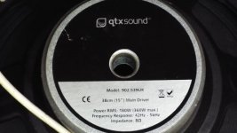
Just pulled the back off "big red" and the speaker is ..... QTX Sound, 15" model 902.539uk. 8ohm. I can stand in front of this thing with 40 watts gonin thru it and NO feedback think its actually a pa speaker this amp sounds gooood. but jeez its heavy, its what did my back in at new years.
Just pulled the back off "big red" and the speaker is ..... QTX Sound, 15" model 902.539uk. 8ohm. I can stand in front of this thing with 40 watts gonin thru it and NO feedback think its actually a pa speaker this amp sounds gooood.
but jeez its heavy, its what did my back in at new years.Attachments
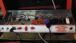
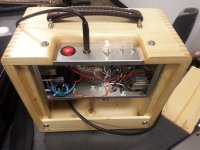
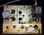
Here is the VERY rough prototype that I did, the most ugly rats nest amp I'd say! My intention was to prototype on the old chassis and then build the final version on a new clean chassis with parts from the $100 parts list. Those are 5881 tubes but the plan was for cheap 12V6s or something similar. It is cathode biased and the 5881s run a bit cold.
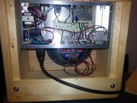
It is built completely out of junk box parts and you can see many combinations of caps and resistors to get the correct value. I have a lot of carbon comp resistors that were given to me that I have no other use for. I used metal film types in the first few stages for lower noise. I think the Sprague PSU caps are from the 1980s but the others are newer. I should find good film caps for the few very old ones that are in there now.
The chassis was a Realistic integrated amp that used oddball 6BM8 outputs that was given to me in the 1980s even when I told the person that I didn't want it. I would have kept it if it was a better design.
The burn marks on the power transformer are from resistors across the transformer that had over heated.
The duct tape is holding on spacers so that I could work on it upside down without smashing the output tubes:
Attachments
Last edited:
- Home
- Live Sound
- Instruments and Amps
- The Hundred-Buck Amp Challenge