I do not agree. I have a Telecaster plugged into an amp with no tone controls, no roll off anywhere (given the guitar frequency response) and it does not sound midrangey. Play through a Fender tone stack and the midrange is dropped out but those frequencies are quieter, just as in a car we sometimes like to hear the bass and treble boosted.The notch in the frequency response of the Fender tone stack was not an accident caused by a "primitive" design. In fact it was the opposite - Fender seems to have been the first to realise that a guitar pickup has a strong peak in its frequency response, and his amps were the first to attempt to compensate for this peak by having a corresponding notch in the amps own frequency response.
So the notch was actually put there to make the overall frequency response of amp + guitar flatter, and take away the midrange peak from the pickup. Other amps of the time had a tendency to sound more nasal or midrangey, because they didn't take out the peak in the guitars frequency response. You can still hear that more nasal tone in amps that don't use a Fender tone stack, for instance in some of the 18 W Marshall clones that use a one-knob tone control. (The one-knob tone control does not have a notch in the frequency response.)
Later Marshall amps modified Fender's tone stack for more gain, but kept the notch in the frequency response, though they shifted its frequency a little to get a somewhat different sound.
Guitar pickups have evolved over the years, so one unanswered question is whether the notch in the Fender tone stack response is in the right place to correct todays Fender guitar pickups or not. Of course all Fender pickups are not the same today, and there are also hundreds of other brands and models on the market. The notch in the amp cannot possibly be in the right place to compensate for all of these different pickups available today.
You can read more about the design and intention of the classic Fender tone-stack here (scroll down to the section on tone controls): GM Arts - Guitar Amplifiers
I've wondered whether a combination of a tunable notch (frequency and Q) and a Baxandall type control, one feeding the other, might make a good guitar amp tone control with the strengths of both Fender's stack and the Baxandall circuit, and more versatility than either one by itself.
-Flieslikeabeagle
And you have to take account the whole package. Fender used open back cabinets, not the best for bass. Marshall used closed back cabinets, mind you, originally a copy of a Fender Bassman, the amp voicing really went for a loop once you throw in some distortion. Cut the bass in the front end of the amp so you do not flub out the bass, roll off the excessive highs of the boosted and distorted signal, get a nice thick midrange.
Basically the amp is used as an effect box. It depends what sound you want out of the amp.
Oscillation that doesn't sound like oscillation
That behavior is very familiar to me. It is so very familiar that I can just about certify that what you are hearing is oscillation. These high frequency oscillations are sometimes above the range of human hearing, but they induce a motorboating effect or some other artifact that is in the range of human hearing and it can express itself in a wide range of acoustic sensations, many of which would not likely create an immediate impression of an "oscillation" if by that word one is thinking "steady whistle-like tone."
The clue is that the sound is only what you are expecting when:
1. The volume is all the way up.
and
2. The tone control all the way down.
With the tone all the way down, you are shorting the high frequencies (and therefore the oscillations) to ground at the output of some stage.
With the volume all the way up, there is no resistance between the grid of some stage and the output of the previous tube feeding that volume pot. So the AC path to ground from that grid is reduced through the previous tube's plate load resistor and its power supply capacitors, which also shunts the high frequency feedback to ground and prevents the oscillation. When you turn down the pot, that introduces a resistance between the output of one tube and the input of another, isolating these two points in the circuit and creating an opening for a capacitance-coupled feedback to induce a voltage in the grid circuit that is now isolated from the "real" signal feeding it. This induced feedback voltage then hijacks the tube, blocking out response to the signal which has been turned down.
It is affected by the tone control circuit because that circuit puts different loads on one of the tubes in the unit depending on the position of the tone control knob and, more importantly (when "all-the-way-down" is not the sweet spot), it changes the phase relationships between the waveforms at different places in the circuit so that the offending feedback is only positive at a certain phase relationship.
These oscillation problems are particularly characteristic of tube circuits precisely because tube circuits tend to be very high impedance high voltage circuits in which very tiny currents can induce large voltages across a resistance, and large voltage swings can induce currents in conductors at a considerable distance away. Sometimes just putting a hand in the vicinity of the conductor radiating the feedback or the one picking it up will load down that through-the-air circuit with a capacitance coupled to ground (your person) enough to silence the oscillation. (This by no means suggests putting your hands indiscriminately into the chassis to find out if it has an effect on things!) Again, what this tells us is that the oscillations happen when a very, very low-power electro-magnetic field event is coupled to a place of high impedance where it is not drained away to ground before taking control of the grid of some tube by means of some ghostly voltage having almost zero power.
When these oscillations interact with the various time-constants created by all the different resistors, capacitors and inductors in the overall circuit, they can create interacting periodic events that modulate each other and/or gate each other and thereby synthesize seemingly unlimited zoos of audibly shrieking life-forms (waveforms).
If you had access to an oscilloscope you could prove this to yourself very quickly. Sometimes you might see high frequency oscillations that nestle themselves only into particular periodic little nooks and crannies of a guitar waveform which adds a ghastly character to the sound of a vibrating string. At its worst, the guitar doesn't sound like itself at all. In a mild instance it sounds like it has a wheezing fret buzz on every note.
Poking around in the wiring with a wooden stick (wearing rubber gloves if you're at all shaky about that) may reveal which wire is too close to the whatchamadoohicky at fault. Or it may not. You can sometimes put small capacitors to good effect across large value plate resistors, across the primary of an output transformer, or between offending points in the circuit and ground. This will roll off your high end, but is sometimes the only way to live with a touchy circuit. A "bright" capacitor between the hot lug of the volume control and the wiper could solve this one while actually boosting the legitimate signal highs as your turn down the volume.
I rather believe that the problem of persistent and stubborn oscillations may have been the original motivation for the development of negative feedback as a design technique.
Point to point can actually lessen these problems depending on which points we're talking about and where they are located in three-dimensional space. Two wires crossing at 90 degrees a half inch apart are less likely to interact than two traces on a circuit board traveling together a sixteenth of an inch apart for eight or ten inches. But if the point-to-point looks like a mess topographically, then it probably is a mess electrically, too.
In all my rat's nest wiring debacles, I've generally found that the offending inter-conductor capacitance is usually not in a geodesic dome of interconnected resistors and capacitors forming a rigid ball around a tube socket, but a stray wire going halfway across the chassis that passes too close to a conductor attached to a grid. You don't happen to notice that the wire going to the tone control pot is passing right across the input jack, do you?
Experiment.
Hi Guys! I have been enjoying this thread for a while. I plan on building several of these amps. The first one I tried is Tubelab's 1.3. Im not nearly as knowledgeable as you are, so Im learning as I go. Im having some issues. The output transformer I assume is wired across the 70 volt taps, using the orange lead as the center tap, with the black and purple going to the power tubes. The amp works, but only with the volume cranked, and the tone all the way down. Otherwise it makes a terrible noise. I don't think its oscillation, but Im not sure. It hums quite a bit, too. I tried to go point to point, but it ended rather messy. Should I start over on a perf board? Opinions?
That behavior is very familiar to me. It is so very familiar that I can just about certify that what you are hearing is oscillation. These high frequency oscillations are sometimes above the range of human hearing, but they induce a motorboating effect or some other artifact that is in the range of human hearing and it can express itself in a wide range of acoustic sensations, many of which would not likely create an immediate impression of an "oscillation" if by that word one is thinking "steady whistle-like tone."
The clue is that the sound is only what you are expecting when:
1. The volume is all the way up.
and
2. The tone control all the way down.
With the tone all the way down, you are shorting the high frequencies (and therefore the oscillations) to ground at the output of some stage.
With the volume all the way up, there is no resistance between the grid of some stage and the output of the previous tube feeding that volume pot. So the AC path to ground from that grid is reduced through the previous tube's plate load resistor and its power supply capacitors, which also shunts the high frequency feedback to ground and prevents the oscillation. When you turn down the pot, that introduces a resistance between the output of one tube and the input of another, isolating these two points in the circuit and creating an opening for a capacitance-coupled feedback to induce a voltage in the grid circuit that is now isolated from the "real" signal feeding it. This induced feedback voltage then hijacks the tube, blocking out response to the signal which has been turned down.
It is affected by the tone control circuit because that circuit puts different loads on one of the tubes in the unit depending on the position of the tone control knob and, more importantly (when "all-the-way-down" is not the sweet spot), it changes the phase relationships between the waveforms at different places in the circuit so that the offending feedback is only positive at a certain phase relationship.
These oscillation problems are particularly characteristic of tube circuits precisely because tube circuits tend to be very high impedance high voltage circuits in which very tiny currents can induce large voltages across a resistance, and large voltage swings can induce currents in conductors at a considerable distance away. Sometimes just putting a hand in the vicinity of the conductor radiating the feedback or the one picking it up will load down that through-the-air circuit with a capacitance coupled to ground (your person) enough to silence the oscillation. (This by no means suggests putting your hands indiscriminately into the chassis to find out if it has an effect on things!) Again, what this tells us is that the oscillations happen when a very, very low-power electro-magnetic field event is coupled to a place of high impedance where it is not drained away to ground before taking control of the grid of some tube by means of some ghostly voltage having almost zero power.
When these oscillations interact with the various time-constants created by all the different resistors, capacitors and inductors in the overall circuit, they can create interacting periodic events that modulate each other and/or gate each other and thereby synthesize seemingly unlimited zoos of audibly shrieking life-forms (waveforms).
If you had access to an oscilloscope you could prove this to yourself very quickly. Sometimes you might see high frequency oscillations that nestle themselves only into particular periodic little nooks and crannies of a guitar waveform which adds a ghastly character to the sound of a vibrating string. At its worst, the guitar doesn't sound like itself at all. In a mild instance it sounds like it has a wheezing fret buzz on every note.
Poking around in the wiring with a wooden stick (wearing rubber gloves if you're at all shaky about that) may reveal which wire is too close to the whatchamadoohicky at fault. Or it may not. You can sometimes put small capacitors to good effect across large value plate resistors, across the primary of an output transformer, or between offending points in the circuit and ground. This will roll off your high end, but is sometimes the only way to live with a touchy circuit. A "bright" capacitor between the hot lug of the volume control and the wiper could solve this one while actually boosting the legitimate signal highs as your turn down the volume.
I rather believe that the problem of persistent and stubborn oscillations may have been the original motivation for the development of negative feedback as a design technique.
Point to point can actually lessen these problems depending on which points we're talking about and where they are located in three-dimensional space. Two wires crossing at 90 degrees a half inch apart are less likely to interact than two traces on a circuit board traveling together a sixteenth of an inch apart for eight or ten inches. But if the point-to-point looks like a mess topographically, then it probably is a mess electrically, too.
In all my rat's nest wiring debacles, I've generally found that the offending inter-conductor capacitance is usually not in a geodesic dome of interconnected resistors and capacitors forming a rigid ball around a tube socket, but a stray wire going halfway across the chassis that passes too close to a conductor attached to a grid. You don't happen to notice that the wire going to the tone control pot is passing right across the input jack, do you?
Experiment.
Hello Everyone, long time no see......As for my long absence from DIY Audio, I have been trying since January to purchase a home......it also came to pass last month that my mother, who was very elderly but in reasonably good health, suddenly passed away. This brought its own sudden set of additional burdens and time-consuming interruptions to the usual daily circumstances around here.
Sorry to hear about your mother. I lost my mother and my mother in law last year. I know how much the little details can absorb all of your spare time. The recent deaths have left me on the other side of the housing market. I now own 2 1/3 houses. Selling a house in Florida isn't easy when the banks own thousands and will undercut you and steal your buyer.
stuffing boxes full of unsorted miscellany, and carting truckloads of them off to a storage unit at regular intervals
We did that for a while when my wife was the manager of said storage facility. She was laid off and the owner removed her employee discount (the rent is now $210/month), so I have been carting truckloads of Tubelab stuff back home. There is stuff everywhere and I can't even get to my workbench. My soldering iron has not been turned on this year. We will be out of that situation in a few months. Look for me and my stuff for sale at the Dayton Hamfest (tubes, transformers, and audio gear).
The output transformer I assume is wired across the 70 volt taps, using the orange lead as the center tap, with the black and purple going to the power tubes.
I chose that transformer because it was cheap and worked. I remember experimenting with the connections to make it work. The amp is on a shelf and I can look to see how it is wired.
That behavior is very familiar to me. It is so very familiar that I can just about certify that what you are hearing is oscillation.
I agree. I believe that you are seeing a high frequency oscillation that is so severe that it is blocking the signal passing through the second stage. Try placing the amp near a TV or radio that is operating and see if it causes interference as the controls are turned.
I tried to go point to point, but it ended rather messy. Should I start over on a perf board?
I wanted a high gain Marshall / Soldano sound, so there is a lot of gain in a small box. The amp was designed to a very low price point, so there is some unique power supply circuitry. Both of these design features place some constraints on the layout. I made the first one on a perf board and then laid out a PC board. It could be done point to point, but it must be done right.
The events that took place last year have prevented me from finishing any of my amps. I didn't even get to post a full explanation of how this one works and explain the design constraints and layout recomendations. I am at work now, so I will put something together in the next few days and post it.
Fender seems to have been the first to realise that a guitar pickup has a strong peak in its frequency response,
The guitar pickup by design is an inductor since it is a coil of wire. It is not even close to a perfect inductor since it has considerable DC resistance, some stray capacitance to ground, and considerable interwinding capacitance. One, two or three of these are interconnected in several possible ways with one or more treble cut controls and fed down a long capacitive cable into an amp with an unknown input impedance and input capacitance. Given this, you can't make a blanket statement about its response but many do have a high frequency peak in the 1 to 4 KHz range followed by a sharp drop off. The cable length moves this peak around quite a bit especially with the guitars controls set wide open.
It is almost 10PM and I just got done with dinner. Working late is a way of life lately.
I will attempt to explain amp 1.3 and the design criteria that affect the layout. This will unfold over a few posts as I do my best to remember an amp that I haven't touched in several months. I got the amp off a shelf and took it out of its cabinet to find that the OPT is not connected to the PC board and the power transformer is missing. That reminded me that I temporarilly borrowed them for an experiment with a mosfet based PI on the perf board version. I will hook them back up and get the amp working, but probably not until this weekend.
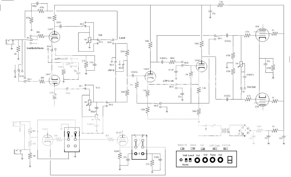
Meanwhile I'll go over a few important points. The preamp has two stages with a lot of gain. The circuitry is relatively conventional with the exception of the tone control. The tone control is a single knob that functions as a treble cut (low pass filter) when the tone pot is wound to the extreme where pins 1 and 2 are shorted. Here R21 is shorted out, C4 is too small to matter, so you have R20 in series with the signal and C5 to ground. This forms a low pass filter. With the pot wound to the other extreme R20, R21 and C4 form a classic high pass filter and C5 is shorted out. In between the two extremes there are two filters with grossly different time constants acting on the signal causing all sorts of frequency dependent phase and amplitude shifts. With the volume control maxed some frequencies will be totally distorted while others are relatively clean.
It is IMPORTANT that the cases of both pots be grounded. This is necessary in most all high gain guitar preamps. The grid stopper resistor should be located close to the tube and the signal path should be as short as possible.
The power supply is a bit unique. THere is the typical bridge rectifier across the output of an isolation transformer. This makes about 155 to 160 volts. C1 is the main filter cap and should be 39 to 47 uF. The heaters are all wired in series and need about 100 volts to light them. Wiring them in series across the secondary with an appropriate droping resistor would seem the logical approach. This doesnt work well with a bridge since the H-K of the end tubes will see large voltage swings violating the ratings and coupling hum into the tubes. Wiring the tubes on the DC supply would impose a large constant DC load (100 mA) requiring a huge filter cap and killing any power supply sag related effects. All of the current is drawn from the DC supply resulting in large pulses of transformer current and a short conduction angle. THis makes the transformer hot, and creates a buzzing noise.
The approach used here feeds the tube string pulsating DC from a seperate set of diodes that does not have a filter cap. This lowers the average voltage on the tubes requiring a smaller dropping resistor. The conduction angle for the heater circuit is 360 degrees and the power factor is nearly 1.0. This works, but the "AC" heater on the preamp tubes causes a faint hum. C10 smooths out the pulsating DC for the preamp tubes only, but in doing so passes the "hum" current to ground. This ground must NOT be signal ground or you will me making hum, not curing it. Ideally the Negative end of C10 should be connected directly to the negative end of C1.
More on grounding next time.
I will attempt to explain amp 1.3 and the design criteria that affect the layout. This will unfold over a few posts as I do my best to remember an amp that I haven't touched in several months. I got the amp off a shelf and took it out of its cabinet to find that the OPT is not connected to the PC board and the power transformer is missing. That reminded me that I temporarilly borrowed them for an experiment with a mosfet based PI on the perf board version. I will hook them back up and get the amp working, but probably not until this weekend.
Meanwhile I'll go over a few important points. The preamp has two stages with a lot of gain. The circuitry is relatively conventional with the exception of the tone control. The tone control is a single knob that functions as a treble cut (low pass filter) when the tone pot is wound to the extreme where pins 1 and 2 are shorted. Here R21 is shorted out, C4 is too small to matter, so you have R20 in series with the signal and C5 to ground. This forms a low pass filter. With the pot wound to the other extreme R20, R21 and C4 form a classic high pass filter and C5 is shorted out. In between the two extremes there are two filters with grossly different time constants acting on the signal causing all sorts of frequency dependent phase and amplitude shifts. With the volume control maxed some frequencies will be totally distorted while others are relatively clean.
It is IMPORTANT that the cases of both pots be grounded. This is necessary in most all high gain guitar preamps. The grid stopper resistor should be located close to the tube and the signal path should be as short as possible.
The power supply is a bit unique. THere is the typical bridge rectifier across the output of an isolation transformer. This makes about 155 to 160 volts. C1 is the main filter cap and should be 39 to 47 uF. The heaters are all wired in series and need about 100 volts to light them. Wiring them in series across the secondary with an appropriate droping resistor would seem the logical approach. This doesnt work well with a bridge since the H-K of the end tubes will see large voltage swings violating the ratings and coupling hum into the tubes. Wiring the tubes on the DC supply would impose a large constant DC load (100 mA) requiring a huge filter cap and killing any power supply sag related effects. All of the current is drawn from the DC supply resulting in large pulses of transformer current and a short conduction angle. THis makes the transformer hot, and creates a buzzing noise.
The approach used here feeds the tube string pulsating DC from a seperate set of diodes that does not have a filter cap. This lowers the average voltage on the tubes requiring a smaller dropping resistor. The conduction angle for the heater circuit is 360 degrees and the power factor is nearly 1.0. This works, but the "AC" heater on the preamp tubes causes a faint hum. C10 smooths out the pulsating DC for the preamp tubes only, but in doing so passes the "hum" current to ground. This ground must NOT be signal ground or you will me making hum, not curing it. Ideally the Negative end of C10 should be connected directly to the negative end of C1.
More on grounding next time.
Could you please describe the sound of your amps in terms of well known recordings?
For example: "Larry Carlton /Steely Dan" type sound
SRV
Lee Ritenour playing his Gibson L5
Robben Ford
etc etc.
I personally am looking for a n amp that will emulate Larry Carlton's sound
Thanks,
Paul
For example: "Larry Carlton /Steely Dan" type sound
SRV
Lee Ritenour playing his Gibson L5
Robben Ford
etc etc.
I personally am looking for a n amp that will emulate Larry Carlton's sound
Thanks,
Paul
Hi...
I designed a guitar amp that costs, here in Brazil, around U$50,00 to build.
I used as preamp an EF184, and as power a 25L5. They give me around 2.2W.
The power transformer i used a 30+30V 800mA, with a doubler for HT, and heaters in series.
If someone wants to take a look...
100Buck.pdf - 4shared.com - document sharing - download
100Buck002.MP4 - YouTube (a very quick and simple sample of the amp)
Image1
Image2
Image3
Image4
Image5
Last edited:
Cool, sounds good also. I did not download your schematic, they want you to sign up and I would rather not.Hi...
I designed a guitar amp that costs, here in Brazil, around U$50,00 to build.
I used as preamp an EF184, and as power a 25L5. They give me around 2.2W.
The power transformer i used a 30+30V 800mA, with a doubler for HT, and heaters in series.
If someone wants to take a look...
100Buck.pdf - 4shared.com - document sharing - download
100Buck002.MP4 - YouTube (a very quick and simple sample of the amp)
Image1
Image2
Image3
Image4
Image5
Santa delivers in the summer.bst sent a care package that will keep me busy for a whole long time. I sure would hate to see what your garage looks like. Thank you sir.http://www.diyaudio.com/forums/members/bst.html
As mentioned in a different thread I am back at it again putting pencil to paper and have a new project. There was some talk elsewhere on the Fender Deluxe 5E3 about getting more clean headroom in the preamp and I though it was time I got more acquainted with the circuit. One of the things that I wanted to know was how much of the sound changes if you alter the volume-tone control connections from the funky 5E3 layout to the more modern layout as in the 6G3. Basically found that all that happens is the input is changed to an output and the output to an input. With a four pole two position switch you can flip between either.
I am also doing one of my switched PI variants, a cathodyne and LTP for this one. Other than the input switching, cathode bias switching, not too much different than what I have discused earlier. I do have some mixing resistors to get away from the 5E3 control interaction but with a switch to get it back and a position to have it but keep some resistance as a grid stopper for the next stage and to kill some gain. A master volume after the PI that can do double duty as a cut knob. Not sure if I am using 12L6's or 12BK5's yet for the output. Hoping for 8W using a 70v line transformer for this one again.
I thought that tube number was familiar but did not have time to look it up. I will be reall interested in seeing how it will turn out. I have a 1760H Hammond OT that I am planning to use with the 8CW5's to get in the 20W range. It has a 6.6k primary and I was going to use the 4 ohm secondary to get 3.3k and run it around 200-250V. I may rethink it knowing they can take a higher plate voltage.
I am also doing one of my switched PI variants, a cathodyne and LTP for this one. Other than the input switching, cathode bias switching, not too much different than what I have discused earlier. I do have some mixing resistors to get away from the 5E3 control interaction but with a switch to get it back and a position to have it but keep some resistance as a grid stopper for the next stage and to kill some gain. A master volume after the PI that can do double duty as a cut knob. Not sure if I am using 12L6's or 12BK5's yet for the output. Hoping for 8W using a 70v line transformer for this one again.
The UL84/45B5 that I mentioned above is a 45 volt 100 mA heater version of the 6CW5. I have used the 6CW5 and other voltage flavors in a few designs over the years. I have learned to respect its screen voltage rating, yet totally ignore the plate voltage spec. My Amp 2.3 runs the screen on 155 volts but the plates see 325 volts. It makes 17 watts at 5% distortion and 22 watts fully cranked with an Antek power toroid for OPT. I have had these tubes to 400 volts by further reducing the screen voltage.
I thought that tube number was familiar but did not have time to look it up. I will be reall interested in seeing how it will turn out. I have a 1760H Hammond OT that I am planning to use with the 8CW5's to get in the 20W range. It has a 6.6k primary and I was going to use the 4 ohm secondary to get 3.3k and run it around 200-250V. I may rethink it knowing they can take a higher plate voltage.
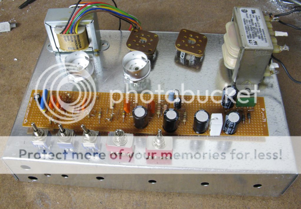
Board is more or less finished, I have some empty space on it and I am not much of one to leave a void. Maybe a fixed bias?, Oh shoot, just remembered the heater elevation, ok almost finished. Here is the chassis with the major bits on top. Getting the heater transformer this afternoon, it will be in front of the power transformer. The switches to configure the amp will be on top of the amp, might have a flip up front on the case, may just have a recessed area. That is if the amp turns out to be well behaved.
Here it is... sorry for delay...Cool, sounds good also. I did not download your schematic, they want you to sign up and I would rather not.
I was going to use 25L6's but now am using 12W6's instead. Now if I decided to made a simple amp for my nephew, wonder what I should do?Here it is... sorry for delay...
")
I was going to use 25L6's but now am using 12W6's instead.
They are similar tubes, so it's down to how you power their heaters. I have done considerable experimentation with series heater strings including a pair of 50L6's and a pair of 12AX7's running on an isolation transformer.
Just wiring them all in series and hanging them across the transformer secondary doesn't work if the B+ rectifier is anything other than a simple half wave. If a full wave bridge is used the heater string and the B- can be different by the peak AC secondary voltage on one half cycle violating the H-K breakdown rating and causing hum.
I tried the scheme used by KEM69 with some success, but this is the typical solid state rectifier with a short conduction angle and corresponding high peak current. This really caused the cheap Triad N-68X to overheat even though the Kill A Watt was reading far less than 50 VA. The solution is not hard in this case. Remove the input capacitor in the heater string supply. In fact I had the best results with no capacitors anywhere in the string except across the first preamp tube's heater. Readjust (or eliminate) the series resistor to keep the same average voltage across the heaters.
This challenge may be over but the experiments aren't. The two series string amplifiers I designed here will be refined further. AMP1.5 is being laid out now on my laptop. I am collecting parts for a possible kit. AMP2.3 is still being tweaked and needs a bit more refinement before it's ready for prime time. It will feature adjustable power levels up to 15 watts. I haven't decided whether or not to switch to 12AX7's for preamp tubes. There is an AMP3.0 in the planning stages and it will not be a series string design. It will have at least 50 watts of power using sweep tubes.
.... if I decided to made a simple amp for my nephew, wonder what I should do?
What to do would depend entirely on your nephew's taste in music and the volume level he needs.
What to do would depend entirely on your nephew's taste in music and the volume level he needs.
Hah! He gets what he gets.
He does not play all that much, gave him a Tele one Christmas and he learned a bit and then went on to play turntables. He still does pick away at home once in a while with no amp. An 8" ans a couple of watts will do him.
They are similar tubes, so it's down to how you power their heaters. I have done considerable experimentation with series heater strings including a pair of 50L6's and a pair of 12AX7's running on an isolation transformer.
Just wiring them all in series and hanging them across the transformer secondary doesn't work if the B+ rectifier is anything other than a simple half wave. If a full wave bridge is used the heater string and the B- can be different by the peak AC secondary voltage on one half cycle violating the H-K breakdown rating and causing hum.
I tried the scheme used by KEM69 with some success, but this is the typical solid state rectifier with a short conduction angle and corresponding high peak current. This really caused the cheap Triad N-68X to overheat even though the Kill A Watt was reading far less than 50 VA. The solution is not hard in this case. Remove the input capacitor in the heater string supply. In fact I had the best results with no capacitors anywhere in the string except across the first preamp tube's heater. Readjust (or eliminate) the series resistor to keep the same average voltage across the heaters.
This challenge may be over but the experiments aren't. The two series string amplifiers I designed here will be refined further. AMP1.5 is being laid out now on my laptop. I am collecting parts for a possible kit. AMP2.3 is still being tweaked and needs a bit more refinement before it's ready for prime time. It will feature adjustable power levels up to 15 watts. I haven't decided whether or not to switch to 12AX7's for preamp tubes. There is an AMP3.0 in the planning stages and it will not be a series string design. It will have at least 50 watts of power using sweep tubes.
I found out about the 12W6 after I picked up some 25L6's. I originally was going to use a 24V transformer for the heaters, found the 12W6's at a decent price, actually aquiring too many tubes, have to stop that. I have more than I will probably ever use.
Being that challenge is over I just want to see what I can come up with but with cost in mind and with the thought others can take away lessons learned. Probably will do work on the house in the summer rather than holed up in the basement, after the current amp that is, want to build a 6 string also.
Being that challenge is over I just want to see what I can come up with but with cost in mind and with the thought others can take away lessons learned
Ditto. Now that the challenge is over there are no rules. This means we can make a $120 amp, sprinkle in some sand where it is beneficial, and maybe exceed the power limit by a little bit. This thread should still be about small low cost amps that others would want to build (IMHO). AMP1.4 gets a mosfet PI and becomes AMP1.5......yeah it gets a switch too, just in case you want to bypass the sand.
want to build a 6 string also.
I built one a few years ago but I didn't like the way it sounded (or didn't) when unplugged. I used a Fender replacement neck, and Fender hardware, and just made the body (from Poplar). So....it's time to make another body.
I made a solid body electric guitar in high school (40+ years ago) out of pine (because it was cheap and I didn't know better). It had a very unique sound and was loud enough to play without an amp. I had it for 30 years or so.
I made the Poplar guitar body after talking to two luthiers about my plans. There will eventually be effects and a small tube preamp inside the body. I will complete the electronics someday, but the guitar is virtually silent without an amp. Way deader than the cheapest plastic coated Squier Strat.
So against the advice of all the experts, I am going to make another pine guitar body. Yes, I know "it won't work" but I have been told that before, and I'm going to do it any way!
I built my cigar box three string and want to do a 6 string. I will be building my own neck, a bit of work but I really liked how the one I made turned out. Basically I want a thin body acoustic, the cigar box body makes enough noise and has its own unique sound. While I have a truss rod for it I am going to try and do it without, I want to preload the neck with strings and then adjust a jig to hold the neck with the same amount of tension without the strings. Then I want to surface the fingerboard. Hopefully it all works out, if not I'll build one with the truss rod.
I am debating on using a wall adapter switched power supply for the heaters in the current amp. I picked one up that puts out 12V and it should be easy enough to adjust it to 12.6V. Long term plans is to convert a computer power supply for the heaters and for the high voltage. My brother converted one to work as a studio flash power supply and I could hit him up for some knowledge.
Experts on pine?
2011 Closet Classic Pine Telecaster® Pro - YouTube
http://www.youtube.com/watch?v=VWG6lSATcR0&feature=related
Last edited:
- Home
- Live Sound
- Instruments and Amps
- The Hundred-Buck Amp Challenge