Question: using an MC as source does the capacitance at the input matter? I can't seem to here a difference between any setting. If this is true could I not replace the capacitors with different value loading resistors for the MC cart?
The last 2 posts are interesting but the above is what I'm trying to get answers for.
The last 2 posts are interesting but the above is what I'm trying to get answers for.
Mine sounds way to tipped up in the treble compared to the Bottlehead w/CCS and the La Pacific. Looking for any mistakes in components tonight. The red board is a little confusing in component placement for R12, C13, C13B. The way I have it is the 2 caps straddling over the top of the R12, is this correct? I have made the mods of R12 to 698K, 220uF C7 with 1k series resistor after SENSEV and 820 R15. I would say that it is a little brighter now than stock circuit. Anyway will try and measure frequency response of Pacific and HO to quantify.
Hallo Hannes,
Gruss Gott,
I'd like a board, please let me know when they are available,
Vielen Danke,
Nick
Hello Hannes
or ...if possible can you PM me the latest Gerber ? I can try and have it made online,
cheers,
Nick
Power supply voltage
Hi,
Understand that a 48 VDC power supply is recommended and some options (power brick / wall-wart type) was also discussed earlier.
http://www.diyaudio.com/forums/analogue-source/242387-octane-phono-preamp-20.html#post4528239
Is there a range of acceptable voltages that will work (for example: from 46 VDC - 50 VDC) or the power supply has to be 48 volts DC only?
Hi everyone,
sorry for being always late in responding to your messages! Of course everyone can have the original Gerber files that came with the article - just mail me and be please a bit patient!
@Freecrowder:
This phono stage has very little input capacitance, which is good as adding caps to it is easy (that's what the dip switches are there for). You didn't mention what kind of cartridge you use, but if it's a true MM that adding capacitance is the way to form the treble to your taste. Please read also the article in LinearAudio, it explains a lot on the background.
The phono stage itself has not a bright or otherwise frequency response colored sound.
Hannes,
Good to see you at the forums.")
Any feedback on my question from the following post?
http://www.diyaudio.com/forums/analogue-source/242387-octane-phono-preamp-57.html#post5236742
Good to see you at the forums.
Any feedback on my question from the following post?
http://www.diyaudio.com/forums/analogue-source/242387-octane-phono-preamp-57.html#post5236742
Thank you!
In the original schematic I added a suitable supply range and I think it is pretty much the range you mention.
If the power supply dc is too low, the regulator cannot work properly. If the power supply dc is too high, the regulator overheats. But a few volts give or take are certainly no problem. In any case one can add a small heatsink to the regulator fet.
Is there a range of acceptable voltages that will work (for example: from 46 VDC - 50 VDC) or the power supply has to be 48 volts DC only?
In the original schematic I added a suitable supply range and I think it is pretty much the range you mention.
If the power supply dc is too low, the regulator cannot work properly. If the power supply dc is too high, the regulator overheats. But a few volts give or take are certainly no problem. In any case one can add a small heatsink to the regulator fet.
Analysis of the High Octane
Hi fellow RIAAlists
I only saw this thread a few days ago, when it appeared on the first page, and I wondered how good is it really?
I set out to investigate the circuit by simulation with LTSPICE, and this post is the first in a short series:
1) The schematic and AC performance
2) Distortion
3) Noise
4) PSRR (Power Supply Rejection Ratio)
5) Statup and shutdown - how does it behave?
6) Suggestion to improvement.
A few comments:
I did not have a LTSPICE model of the 2sc2547, so I tried with 2sc2240 and 2sc3329. The would be my first choice, unfortunately the LTSPICE model has some issues in transient analysis, so I used the 2sc3329. Further I did not have a model for the DN2540, so I substituted with a resistor. This means that specifically the distortions I've found probably would be improved.
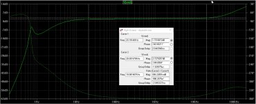
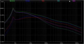
AC Performance:
I general it performs quite well with except maybe above 10kHz, where the output rises. Otherwise very nice.
One important observation: at approximately 0.7Hz there seems to be some form of resonans - not so good - I'll get back to that later.
Hi fellow RIAAlists
I only saw this thread a few days ago, when it appeared on the first page, and I wondered how good is it really?
I set out to investigate the circuit by simulation with LTSPICE, and this post is the first in a short series:
1) The schematic and AC performance
2) Distortion
3) Noise
4) PSRR (Power Supply Rejection Ratio)
5) Statup and shutdown - how does it behave?
6) Suggestion to improvement.
A few comments:
I did not have a LTSPICE model of the 2sc2547, so I tried with 2sc2240 and 2sc3329. The would be my first choice, unfortunately the LTSPICE model has some issues in transient analysis, so I used the 2sc3329. Further I did not have a model for the DN2540, so I substituted with a resistor. This means that specifically the distortions I've found probably would be improved.
AC Performance:
I general it performs quite well with except maybe above 10kHz, where the output rises. Otherwise very nice.
One important observation: at approximately 0.7Hz there seems to be some form of resonans - not so good - I'll get back to that later.
Attachments
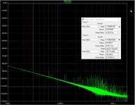
Analysis of the High Octane - Distortion
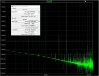
Distortion
I only simulated at 30Hz (very high gain), 6kHz - the last frq where you can hear the 3rd harmonic at 18kHz, and 1kHz with input turned up to +20dB.
As you can see from the FFT plots, it is very well behaved. Even at +20dB it is well behaved.
Distortion
I only simulated at 30Hz (very high gain), 6kHz - the last frq where you can hear the 3rd harmonic at 18kHz, and 1kHz with input turned up to +20dB.
As you can see from the FFT plots, it is very well behaved. Even at +20dB it is well behaved.
Attachments
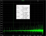
Analysis of the High Octane - Noise
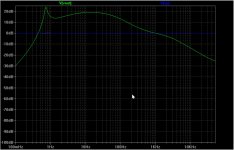
From this graph you may observe two things:
1) In the audio band (20Hz-20Khz) the main noise-contributor is the cartridge itself, as it should be.
2) Below app 17Hz the noise is defined by Q1 and R8. Further it get accentuated by the resonance mentioned earlier. You can't hear this, but if you but finger on the woofer, you most likely will feel it if the volume is set at "realistic" level - whatever that is.
Attachments
Analysis of the High Octane - PSRR
This is where this circuit shows a spot of bad behavor. Below 1kHz the correct description would be Power Supply Amplification Ratio! This is not exactly stellar performance, it shows how vital it is with a *very* quit PSU.
This is where this circuit shows a spot of bad behavor. Below 1kHz the correct description would be Power Supply Amplification Ratio! This is not exactly stellar performance, it shows how vital it is with a *very* quit PSU.
Attachments
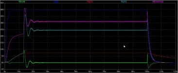
Analysis of the High Octane - Startup
I have not simulated the original PSU, rather supplied my own design. It is first of all completely discrete - no ICs! And it's a shunt regulator as in the original.
Seen from the right, there is voltage doubler rectifier and reservoir capacitors. Next follows a constant current generator, build around Q201 and Q202. Then follow a simple RC-filter (C203 and R204)to remove HF noise. And yes, they are in the correct order! Then we have a power-Zener with a large transistor (Q203) that ensures it can cope with dissipation if it should be tested without load.
Finally there is a lo-pass filter build as a second order Sallen-Key filter.
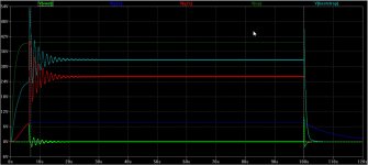
The actions when power is applied is problematic to say the least, but not very different from other single supply circuits. Capacitors have to get charged before things settle down. But in this case there is a (damped) oscillation at app 0.7Hz - same frq as the peak in plot in my first post.
What happens is basically this: when power is applied, Q1 is off as there is no bias. Q2 then is turned on hard - it saturates - through R4, now C8 slowly charges up through r10 and R9. Eventually Q1 is turned on, removing the base current from Q2 which opens. Q3 then saturates and with the aid of the C10 bootstrap, the base of Q3 actually rises above the power supply. Result: a massive spike at the output.
Also, there is quite a spark when power is removed at 100 second. In other words you do not want to have your input selector on grammophone when turning ths amplifier on or off!
I have not simulated the original PSU, rather supplied my own design. It is first of all completely discrete - no ICs! And it's a shunt regulator as in the original.
Seen from the right, there is voltage doubler rectifier and reservoir capacitors. Next follows a constant current generator, build around Q201 and Q202. Then follow a simple RC-filter (C203 and R204)to remove HF noise. And yes, they are in the correct order! Then we have a power-Zener with a large transistor (Q203) that ensures it can cope with dissipation if it should be tested without load.
Finally there is a lo-pass filter build as a second order Sallen-Key filter.
The actions when power is applied is problematic to say the least, but not very different from other single supply circuits. Capacitors have to get charged before things settle down. But in this case there is a (damped) oscillation at app 0.7Hz - same frq as the peak in plot in my first post.
What happens is basically this: when power is applied, Q1 is off as there is no bias. Q2 then is turned on hard - it saturates - through R4, now C8 slowly charges up through r10 and R9. Eventually Q1 is turned on, removing the base current from Q2 which opens. Q3 then saturates and with the aid of the C10 bootstrap, the base of Q3 actually rises above the power supply. Result: a massive spike at the output.
Also, there is quite a spark when power is removed at 100 second. In other words you do not want to have your input selector on grammophone when turning ths amplifier on or off!
Attachments
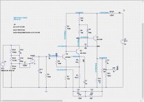
High Octane mrk II
Mrk II
I have found that if you make the changes as can be seen in the schematic below, the problems (sub sonic noise, PSRR and the 0.7Hz resonance) are reduced
I suggest the following component changes:
from to
R1 100k 300k gives 47k input resistance in parallel with R8
R8 100k 56k reduces noise from R8 and Q1
C1 1u 10u maintains contact with the cartridge further down,
reduces noise
C8 1m 2.2m all but eliminates the 0.7 resonance => reduces noise
C9 10p 47p for added stability
C11 1u 10u 1u cannot drive an input at 10kOhm
R16 40k2 100k R16 is there only to insure the potential at the output
is zero, not a filter
R5 47 100 Just be sure there is no oscillation in Q3.
Further I have added
R17 2k2 R17 & C7: PSU filter, improves PSRR
C7 220u Could be larger for better filtering
Attachments
-
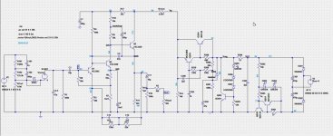 High Octane - schematic + PSU mrk II.jpg293 KB · Views: 196
 -
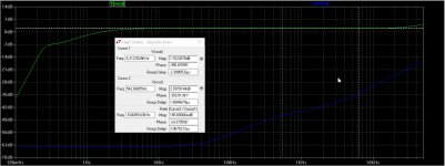 High Octane - AC performance mrk II.jpg207 KB · Views: 201
 -
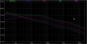 High Octane - noise mrk II.jpg156.4 KB · Views: 99
 -
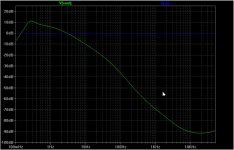 High Octane - PSRR mrk II.jpg146.7 KB · Views: 95
 -
 High Octane - Startup - shutdown mrk II.jpg128.3 KB · Views: 105
 -
High Octane - diyaudio II.asc12.1 KB · Views: 56
- Home
- Source & Line
- Analogue Source
- The high octane phono preamp