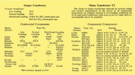
Simon, since the transformers are PP you need to stick with a PP design, or buy new iron.
You can measure the transformers to determine the turns ratio, and thus the impedance matching.
The Mullard 5-10 article calls out different Hinchley transformers (5133), but in all probablilty the 51/507 are similar. Easy enough to measure the UL tap ratio along with the rest of the characteristics. They could be 25% as that tap ratio is listedin the 5-10 article, but most likely will be around 40% (43%) as that gives lower distortion.
Too bad Tamura does not have any historical info on their web site (tamura bought out Hinchley and discontinued the audio output transformers from what I find on the web).
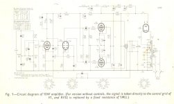
You have the resistor values from the Mullard schematic (exact copy right?). So why not just triode strap the EF86 to reduce the gain a little bit and rebuild the thing with the rest of the design intact? Seems like it would make a fine little amp. You could tweak the FB if you like as well. That is what I would do if they were mine.
I think this type of refurb, Is the way 5-10's are 'modernised'.
Hi Mike
Thanks for your thoughts on the tiny tube amps.
The reason the amps have sat in my garage for 20 years, is not wanting to dump them, but not knowing what to do with them.
I think the amps would have been there another 20 years if it wasn't for the Net and members at diyAudio.
When I started doing diy audio, I had the public library and one electronics mag a month as my sources of information, I have met more enthusiasts like my self in a month here on the site, than I have in 30 years of soldering away in my garage (haven't picked up a soldering iron in a month, I've been on the net all the time ! Oh well, it helps to have a bit of a plan worked out before you setout, otherwise you get lost, right ?).
I think you have suggested the 'mod'ernisation that I have heard mentioned in passing in several other forums here in the UK, but sadly no details of what was done exactly were mentioned.
Triode strapping the EF86 seemed to be the handle I got on it, along with I think the ability to reduce feedback.
After a good nights sleep and a break from amps and the net, I am now thinking that starting from scratch with just the iron and tubes would be wrong, and I would be essentialy loosing a couple of 'classics' in the process.
So I reckon modding the input, replacing the caps, connectors, valve bases and cleaning them up a bit looks like the way to go.
It's still being assumed that these MA-12's are Mullard 5-10's, although still don't have a 'Heathkit' schematic or constructors manual for them.
I do have two very poor copys of the Mullard 5-10 schematic however, and I guess even if there were tiny differences in the schematics, the iron and tubes are the same so this would not be a problem.
If I can find details of the triode strapping mod, I will redraw the poor quality schematics I have, with this mod, and what I can see in the schematics I have and from looking at the amps.
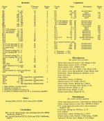
Resistor values are interesting, most (but not all) are readable from the schematics.
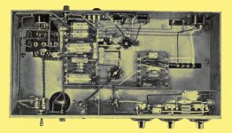
Inside the amps, stripe colours have faded a bit and paint flaked off.
I don't have a lot of experiance with older resistors and the value 'drifting' some report so I am unsure whether to replace these or not.
The diyer who made these obviously got them working just fine, but the construction inside is an absolute mess, and replacement parts have also been thrown in ad-hoc as well (would be nice if they weren't deathtraps !).
I am thinking a new chassis for the amps would mean I could get connector and capacitor mounting holes the right size easily, and space out the layout a bit more and improve the hum situation a bit.
This would obviously loose a bit of the 'look' of the amps, but since the Mullard 5-10 was a 'generic' design produced in a thousand different ways, I don't feel that sentimental or nostalgic about the chassis, if I could benefit the amps by making a new one, I think I probably should.
I almost feel like a keen diyer back in 1954 at the moment !!! a lot of whom would have made their own chassis.
Thank for your interest In the project Mike.
Cheers... Simon...")
You have the resistor values from the Mullard schematic (exact copy right?). So why not just triode strap the EF86 to reduce the gain a little bit and rebuild the thing with the rest of the design intact? Seems like it would make a fine little amp. You could tweak the FB if you like as well. That is what I would do if they were mine.
Hi Mike
Thanks for your thoughts on the tiny tube amps.
The reason the amps have sat in my garage for 20 years, is not wanting to dump them, but not knowing what to do with them.
I think the amps would have been there another 20 years if it wasn't for the Net and members at diyAudio.
When I started doing diy audio, I had the public library and one electronics mag a month as my sources of information, I have met more enthusiasts like my self in a month here on the site, than I have in 30 years of soldering away in my garage (haven't picked up a soldering iron in a month, I've been on the net all the time ! Oh well, it helps to have a bit of a plan worked out before you setout, otherwise you get lost, right ?).
I think you have suggested the 'mod'ernisation that I have heard mentioned in passing in several other forums here in the UK, but sadly no details of what was done exactly were mentioned.
Triode strapping the EF86 seemed to be the handle I got on it, along with I think the ability to reduce feedback.
After a good nights sleep and a break from amps and the net, I am now thinking that starting from scratch with just the iron and tubes would be wrong, and I would be essentialy loosing a couple of 'classics' in the process.
So I reckon modding the input, replacing the caps, connectors, valve bases and cleaning them up a bit looks like the way to go.
It's still being assumed that these MA-12's are Mullard 5-10's, although still don't have a 'Heathkit' schematic or constructors manual for them.
I do have two very poor copys of the Mullard 5-10 schematic however, and I guess even if there were tiny differences in the schematics, the iron and tubes are the same so this would not be a problem.
If I can find details of the triode strapping mod, I will redraw the poor quality schematics I have, with this mod, and what I can see in the schematics I have and from looking at the amps.
Resistor values are interesting, most (but not all) are readable from the schematics.
Inside the amps, stripe colours have faded a bit and paint flaked off.
I don't have a lot of experiance with older resistors and the value 'drifting' some report so I am unsure whether to replace these or not.
The diyer who made these obviously got them working just fine, but the construction inside is an absolute mess, and replacement parts have also been thrown in ad-hoc as well (would be nice if they weren't deathtraps !).
I am thinking a new chassis for the amps would mean I could get connector and capacitor mounting holes the right size easily, and space out the layout a bit more and improve the hum situation a bit.
This would obviously loose a bit of the 'look' of the amps, but since the Mullard 5-10 was a 'generic' design produced in a thousand different ways, I don't feel that sentimental or nostalgic about the chassis, if I could benefit the amps by making a new one, I think I probably should.
I almost feel like a keen diyer back in 1954 at the moment !!! a lot of whom would have made their own chassis.
Thank for your interest In the project Mike.
Cheers... Simon...
Attachments
Thanks for the tip on the replacement caps.
Hi The Gimp
Thanks for the tip on the caps.
I am making a parts list for the amps and I think your right, switching on with leaky lectro's and melted wax is not a great move.
I have probably got some of the small values in my parts box already, so I will have a sift through to check this out.
The big'uns I will have to order in.
I seem to have picked up from somewhere that when using a tube rectifier (which my other valve projects haven't used before) such as the GZ34, you can't just bump up the values as you can in SS. I believe this is something to do with damaging the rectifier if the value is too high.
What I'm not sure of is whether this applies to the secondry caps after the resistor or inductor in the power supply. I think the limit on the cap size is to limit the charging current through the GZ34, so as not to cause damage to it.
The original Mullard 5-20 used a smaller B9 rectifier, but I think Heathkit threw in a bigger one to allow the powering of their optional preamps using the HT/filament outlet on the back of the monoblocks.
It's good to have 2 amps I think, as I can strip one, and still have the other as a referance.
Thanks for your message The Gimp
Cheers... Simon...
New caps are available in limited values. You might not be able to get all the segments in one package, but could replace the originals and get two or three segments such that you only had to add one additional cap under the chassis.
I know AES has them here in the US made by CE (or at least marked by CE), and I suspect that there are sources in europe as well.
Once you identify the values of the caps, I'm sure someone can chime in with a potential source.
I would recommmend not running the 'good' amp till you reform the caps if it has been setting for several years.
Hi The Gimp
Thanks for the tip on the caps.
I am making a parts list for the amps and I think your right, switching on with leaky lectro's and melted wax is not a great move.
I have probably got some of the small values in my parts box already, so I will have a sift through to check this out.
The big'uns I will have to order in.
I seem to have picked up from somewhere that when using a tube rectifier (which my other valve projects haven't used before) such as the GZ34, you can't just bump up the values as you can in SS. I believe this is something to do with damaging the rectifier if the value is too high.
What I'm not sure of is whether this applies to the secondry caps after the resistor or inductor in the power supply. I think the limit on the cap size is to limit the charging current through the GZ34, so as not to cause damage to it.
The original Mullard 5-20 used a smaller B9 rectifier, but I think Heathkit threw in a bigger one to allow the powering of their optional preamps using the HT/filament outlet on the back of the monoblocks.
It's good to have 2 amps I think, as I can strip one, and still have the other as a referance.
Thanks for your message The Gimp
Cheers... Simon...
Attachments


Hi Mosquito, thanks for buzzing by with the caps tip !
Hi Mosquito
Will check out 'ask jan first', def need some new caps for these little babys.
What is your Avatar ?
Can't quite make it out, It looks a bit like a mustard pot we have here with a small long handled spoon ?
Just thought I'd ask !
Cheers... Simon...
Hi, I believe this guy at the site "ask jan first" carries multi segment caps..
Hi Mosquito
Will check out 'ask jan first', def need some new caps for these little babys.
What is your Avatar ?
Can't quite make it out, It looks a bit like a mustard pot we have here with a small long handled spoon ?
Just thought I'd ask !
Cheers... Simon...
Reconfigure EF86 or new input tube ?
Hi Scott
It looks like stick with the original Mullard design, and reconfigure the EF86 or find a new input tube like the 12BH7 or similar you suggested is the way to go, keep the feedback, but reduce it.
Some of the Russian tubes like Salas used in his 'valve itch' look interesting, either B9's or Octal, he says they are very low microphonic, and good prices as well.
Could chuck in a 300b at the front just for laughs I suppose !!!
Cheers ...Simon...
Simon,
You could drop the ef86 from the amp and replace it with a 12bh7 or similar lower mu tube. With the lower mu tube, the GFNB can be minimized to a decent level. The input tube is nice to have as it provides a convient means to inject the GNFB.
Hi Scott
It looks like stick with the original Mullard design, and reconfigure the EF86 or find a new input tube like the 12BH7 or similar you suggested is the way to go, keep the feedback, but reduce it.
Some of the Russian tubes like Salas used in his 'valve itch' look interesting, either B9's or Octal, he says they are very low microphonic, and good prices as well.
Could chuck in a 300b at the front just for laughs I suppose !!!
Cheers ...Simon...
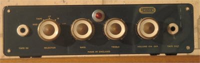
"What's 'The Verdik' on the Verdi ?" or "What's the Verdi on 'The Verdik ?"
Hi teeny tube amp fans...
If the EL84 was good enough for The Beatles, then it's good enough for you !...

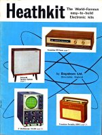
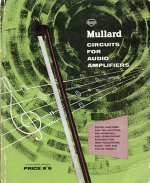
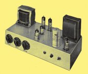
Just found another Mullard 5-10 clone for the collection...
So I thought I'd share a few pics & see what the verdict on 'The Verdik' is...
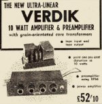
£52/10- was pretty big bucks back in the day...
So I'm guessing the venerable valved 'Verdik' was total 'high-end' kit.
It was NEW and Ultra-linear, with grain-orientated core transformers, 0.1% distortion -
 - & a wiz bang
  EF86 preamplifier as well (even had a analogue tape in/out, cool !)...
 ..
..
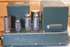
Nice pop-rivet work on the chassis, shame they didn't chrome it up a bit if you ask me.
Never mind, it's not for putting on a pedestal like a Faberge egg,. it's for listening to music with.
My verdict would have to be 5 ***** .Looks like a winner.
Anyone got one I can audition for a week ?.
Cheers...Simon...
Hi teeny tube amp fans...
If the EL84 was good enough for The Beatles, then it's good enough for you !...
Just found another Mullard 5-10 clone for the collection...
So I thought I'd share a few pics & see what the verdict on 'The Verdik' is...
£52/10- was pretty big bucks back in the day...
So I'm guessing the venerable valved 'Verdik' was total 'high-end' kit.
It was NEW and Ultra-linear, with grain-orientated core transformers,
0.1% distortion -- & a wiz bang EF86 preamplifier as well (even had a analogue tape in/out, cool !).....Nice pop-rivet work on the chassis,
shame they didn't chrome it up a bit if you ask me.Never mind, it's not for putting on a pedestal like a Faberge egg,.
it's for listening to music with.My verdict would have to be 5 *****
.Looks like a winner.Anyone got one I can audition for a week ?.
Cheers...Simon...
Attachments
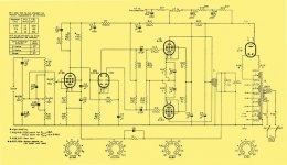
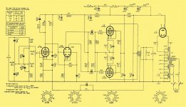
Bad resolution on the schematic in post #43, try this one.
This schematic is VERY clear and high res of the Mullard 5-10, sorry about the last one it looked like pea-soup fog !.
Simon...
This schematic is VERY clear and high res of the Mullard 5-10, sorry about the last one it looked like pea-soup fog !.
Simon...
Attachments
Just found another Mullard 5-10 clone for the collection...
So I thought I'd share a few pics & see what the verdict on 'The Verdik' is...
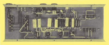
That's a cute little amp, just an unfortunate name. They really packed everything close together didn't they.
jeff
That's a cute little amp, just an unfortunate name. They really packed everything close together didn't they.
jeff
Linn would love the naming.
Linn would love the naming.
I'm surprised they haven't used it for something.
jeff
The world's teeniest, tiny tube amp !
Hi Jeff
They certainly did pack it in on that one.
You should see the inside of my MA-12's, deathtrap waiting to happen.
Heathkit certainly didn't want to waste any steel on that one either.
They should have made it out of the dreaded carbon-fibre, at least it wouldn't be 20% iron oxide by now !
The 'Verdik' looks pretty tough though, it looks like someones been giving it a bit of a bashing.
Have you busted a chain-stay for my tonearm yet ?
Simon...
If you thought that one was cute wait till you see the next one.
*saves both steel & ally (no carbon either, part from a few toasted resistors).
*VERY cheap on valve replacements.
*economical on electricity (windpower option not available when it first came out).
*small carbon footprint (no pun intended), small actual footprint (minimum shelf space wasted that could be stuffed with records).
*won't waste batterys (unless you happen to have the odd 200 or so AA's knocking about & only want to listen to one 7" single).
*more rugged than an Amstrad system.
& won't have the neighbours banging on your front door unless you have 20ft horn speakers.
What is this amazing amp?
I think I'm going to sell my MA-12's and get one (or maybe 2 if I 'upgrade' from mono)
You could probably power it from a high tech carbon-fibre dynamo, for on bike tube sound.
I want one.
Simon..........................................................................................
That's a cute little amp, just an unfortunate name. They really packed everything close together didn't they.
jeff
Hi Jeff
They certainly did pack it in on that one.
You should see the inside of my MA-12's, deathtrap waiting to happen.
Heathkit certainly didn't want to waste any steel on that one either.
They should have made it out of the dreaded carbon-fibre, at least it wouldn't be 20% iron oxide by now !
The 'Verdik' looks pretty tough though, it looks like someones been giving it a bit of a bashing.
Have you busted a chain-stay for my tonearm yet ?
Simon...
If you thought that one was cute wait till you see the next one.
*saves both steel & ally (no carbon either, part from a few toasted resistors).
*VERY cheap on valve replacements.
*economical on electricity (windpower option not available when it first came out).
*small carbon footprint (no pun intended), small actual footprint (minimum shelf space wasted that could be stuffed with records).
*won't waste batterys (unless you happen to have the odd 200 or so AA's knocking about & only want to listen to one 7" single).
*more rugged than an Amstrad system.
& won't have the neighbours banging on your front door unless you have 20ft horn speakers.
What is this amazing amp?
I think I'm going to sell my MA-12's and get one (or maybe 2 if I 'upgrade' from mono)
You could probably power it from a high tech carbon-fibre dynamo, for on bike tube sound.
I want one.
Simon...
.......................................................................................Linn would love the naming.
Ah Mr. Salas
Yeah smart ***, I missed that one.
I agree, it's just their kind of Lingo.
Just finding the photo of the world's #1 cutest amp............
Simon...
THE WORLDS A#1 CUTEST AMP EVER !!!
OK folks if your watching on a 50 zillion" carbon-fibre monitor - THIS IS NOT LIFE SIZE !
I'm surprised. jeff
OK folks if your watching on a 50 zillion" carbon-fibre monitor - THIS IS NOT LIFE SIZE !
Attachments
Have you busted a chain-stay for my tonearm yet ?
Not yet. You'd probably really like the seat stays. They have a lovely "S" shape to them.
If you thought that one was cute wait till you see the next one.
I'm not particularly superstitious, but all three of the knobs in that picture are pointing to "six".

Have you ever come across the G.E.C. "912-PLUS"?
jeff
The Writings On The Wall - that's the 'Verdik'
Hi VK
I'm not particularly superstitious either (except when I spin Stevie's 7).
Just after your observation about the settings on the Mullard 3-3's audiophile stepped attenuator and graphic equaliser came through, I had a problem.
HAL the digital voice inside my vintage laptop informed me I had just suffererd a serious unrecoverable error in my KERNAL, Firefox told me it was 'embarressed' (which is ilogical Captain, it displays diyAudio on the ships carbon-fibre monitor, but has no emotions).
Seems like there might be a ghost in the machine.
The numerals in Mullard's nomenclature summed also = 6, multiplied they = 9, witch is an upside-down 6, divided they = 1 witch is the worlds #1 cutest amp & minused they = 0 witch is exactly what I got on HAL last night 000000.
Anyway not being one to be put off that easily, I adjusted the 0.0000001 c/w sink on my vintage Pentium thingy (I don't know if you knew but those things aren't round ! they're square and have more than 8 or 9 pins ! very confusing) and was good to go again this morning.
Hope your OK Jeff and nothings happened like a catastrophic stay snaping crash or anything, am just asking as I burnt my baked potato last night while trying to get back on the 666 (sorry, typo) WWW last night.
Back to the serious business of 'Hi-Fi' now though.
Funny you should mention the GEC 912-plus, I downloaded the GEC book of tube amps from Pete Millett's exellent site yesterday (haven't had a chance to look at it yet but I guess the 912 might be in there).
Got any pics of it ?
Had REVELATIONS (oh dear) on the Mullard 5-10 (5+1+0=6).
If you build the optional front end, of passive graphic equaliser & attenuator, this takes the input level from 40mv up to about 400-600mv, which is a lot more reasonable sens level, and means the design could be made exactly as the original, which is appealing (my MA-12's are EQ-less, no 6's on them).
The bass & treb use 2 Meg!!! pots, and the vol 1 Meg!!!, so would probably have to be stepped, as me thinks decent pots may be hard to get (I think they're doing this so the EQ caps are very small).
Cheers... Simon...
I'm not particularly superstitious, but all three of the knobs in that picture are pointing to "six".
Have you ever come across the G.E.C. "912-PLUS"?
jeff
Hi VK
I'm not particularly superstitious either (except when I spin Stevie's 7).
Just after your observation about the settings on the Mullard 3-3's audiophile stepped attenuator and graphic equaliser came through, I had a problem.
HAL the digital voice inside my vintage laptop informed me I had just suffererd a serious unrecoverable error in my KERNAL, Firefox told me it was 'embarressed' (which is ilogical Captain, it displays diyAudio on the ships carbon-fibre monitor, but has no emotions).
Seems like there might be a ghost in the machine.
The numerals in Mullard's nomenclature summed also = 6, multiplied they = 9, witch is an upside-down 6, divided they = 1 witch is the worlds #1 cutest amp & minused they = 0 witch is exactly what I got on HAL last night 000000.
Anyway not being one to be put off that easily, I adjusted the 0.0000001 c/w sink on my vintage Pentium thingy (I don't know if you knew but those things aren't round ! they're square and have more than 8 or 9 pins ! very confusing) and was good to go again this morning.
Hope your OK Jeff and nothings happened like a catastrophic stay snaping crash or anything, am just asking as I burnt my baked potato last night while trying to get back on the 666 (sorry, typo) WWW last night.
Back to the serious business of 'Hi-Fi' now though.
Funny you should mention the GEC 912-plus, I downloaded the GEC book of tube amps from Pete Millett's exellent site yesterday (haven't had a chance to look at it yet but I guess the 912 might be in there).
Got any pics of it ?
Had REVELATIONS (oh dear) on the Mullard 5-10 (5+1+0=6).
If you build the optional front end, of passive graphic equaliser & attenuator, this takes the input level from 40mv up to about 400-600mv, which is a lot more reasonable sens level, and means the design could be made exactly as the original, which is appealing (my MA-12's are EQ-less, no 6's on them).
The bass & treb use 2 Meg!!! pots, and the vol 1 Meg!!!, so would probably have to be stepped, as me thinks decent pots may be hard to get (I think they're doing this so the EQ caps are very small).
Cheers... Simon...
Attachments
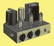
Here's a close-up of the EQ & volume control.
RV 28 - Treble = +10dB to -10dB @ 10kHz
RV 30 - Bass = +11dB to -5dB @ 20Hz
The input sensitivity is 40mV without EQ section & 600mV with EQ section.
Feedback from the output transformer to the EF86 cathode is 26dB.
RV 28 - Treble = +10dB to -10dB @ 10kHz
RV 30 - Bass = +11dB to -5dB @ 20Hz
The input sensitivity is 40mV without EQ section & 600mV with EQ section.
Feedback from the output transformer to the EF86 cathode is 26dB.
Attachments
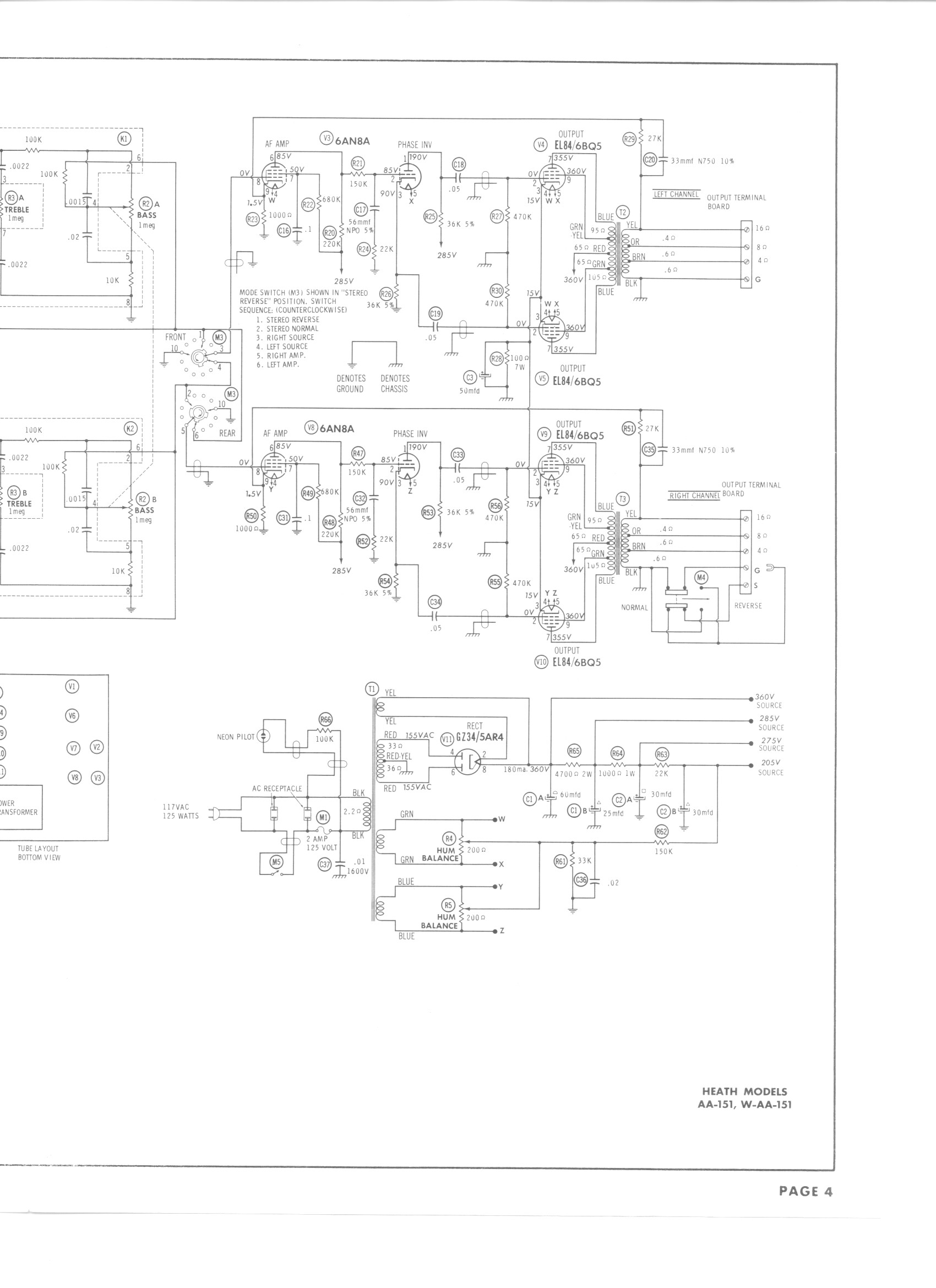
According to most data sheets I've seen the EL84/6BQ5 is only good for 300 V on the plates and screens. The schematic for the AA-151 here shows 355 V on the plates, and 360 V on the screens - Yikes! All I can figure is either the plate current is low, or those poor tubes are being beat to death!
Am I missing something here?
Am I missing something here?
- Status
- This old topic is closed. If you want to reopen this topic, contact a moderator using the "Report Post" button.
- Home
- Amplifiers
- Tubes / Valves
- The Heathkit MA-12 - A Mullard 5-10 In Disguise