Hi everyone,
This will be my first full-range project -- have ordered a pair of modded FE126E drivers from Dave (I felt I had to buy something from him after getting the plans for free!), and I'll be building the enclosures (with the curved rear but without the rear diffuser and large front baffle) over the summer -- hopefully finished by the end of August.
Dave told me that he has "the feeling that the current plans are pretty close to an officially releasable version" -- so I guess I'll not hang around if the folding is unlikely to change.
A few questions though --
- Is it worth lining the chamber and horn channels with felt or something similar? -- would need to get this right first time, as I intend on glueing the side panel permanently afterwards!
- for the tuning of the chamber size, any recommendations (small bags of sand...?). Seems that the best size is somewhere between 1.2 and 1.8 Litres?
- finally (and without getting into a cable debate ), what gauge hook-up wire for attaching the drivers to the binding posts?
all best,
stefan
This will be my first full-range project -- have ordered a pair of modded FE126E drivers from Dave (I felt I had to buy something from him after getting the plans for free!), and I'll be building the enclosures (with the curved rear but without the rear diffuser and large front baffle) over the summer -- hopefully finished by the end of August.
Dave told me that he has "the feeling that the current plans are pretty close to an officially releasable version" -- so I guess I'll not hang around if the folding is unlikely to change.
A few questions though --
- Is it worth lining the chamber and horn channels with felt or something similar? -- would need to get this right first time, as I intend on glueing the side panel permanently afterwards!
- for the tuning of the chamber size, any recommendations (small bags of sand...?). Seems that the best size is somewhere between 1.2 and 1.8 Litres?
- finally (and without getting into a cable debate
), what gauge hook-up wire for attaching the drivers to the binding posts?all best,
stefan
ssmith said:Dave told me that he has "the feeling that the current plans are pretty close to an officially releasable version" -- so I guess I'll not hang around if the folding is unlikely to change.
I am just about ready to release the "wedgie" folding. This is actually the same folding but acheives the taper in the 1st 2 sections in a different manner. This will be called 1.4.0w and doesn't displace 1.4.0, just different.
I saw our 1.4.0w builds (with only 1 side) in the back of Chris' truck yesterday.
- Is it worth lining the chamber and horn channels with felt or something similar? -- would need to get this right first time, as I intend on glueing the side panel permanently afterwards!
- for the tuning of the chamber size, any recommendations (small bags of sand...?). Seems that the best size is somewhere between 1.2 and 1.8 Litres?
- finally (and without getting into a cable debate
Playing with damping and getting the CC just right seem to be the challenges we have yet to get nailed. The CC range should maybe be extended a bit on the top end. We have been just using the 2.3 ish litre small camber. Once other development slows down we will have a chance to play more with CC (sand bags is a good idea)
We use a single pair of Cat 5 cable in our builds. (ie 24guage very high purity solid copper
dave
gexter said:Whats a matrix structure?
I was wondering the same thing. When i here the term i think of the inside of the B&W nautilus series speakers. It certainly has been suggested that the inside of the CC be made irregular.
dave
I have added the 1.4.0 Wedgie plans as an appendix.
http://www.planet10-hifi.com/a140-plans.html
This differs from the 1.4.0 version in the manner in which the taper is achieved in the 1st 2 sections. Originally conceived to simplify the angle cuts needed to build the horn, we believe is has potential sonic benefits as well. We have a pair of these under construction.
dave
tinitus said:I wonder if anyone has ever considered making the CC with matrix structure ??, or maybe it will loose compression ??
Anyone please correct me if I am wrong but, the CC doesn't refer to "compression" at all. It is a coupling chamber. There is no compression taking place. In fact it tends to drive me nuts when I hear people calling it a "compression chamber". The only purpose the coupling chamber serves is to provide an upper-frequency cut-off point so that higher frequencies are disallowed from entering the horn. TMTC
Tom
Harderror said:Anyone please correct me if I am wrong but, the CC doesn't refer to "compression" at all. It is a coupling chamber. There is no compression taking place. In fact it tends to drive me nuts when I hear people calling it a "compression chamber". The only purpose the coupling chamber serves is to provide an upper-frequency cut-off point so that higher frequencies are disallowed from entering the horn. TMTC
Old terms die hard. In a front loaded horn -- particularily in a HF unit it actually is a compression chamber. And even in a rear-loaded horn it is as well, since we want a higher air density to better couple the samll diaphram to the outside world. The horn goes from high pressure, small area, to low pressurem large area. Consider how the stiffness of the air is used in an acoustic suspension enclosure to provide a larger part of the driver compliance, Now in a daline it would definitly be called a couping chamber. Since these little rear-loaded horns are all actually horn/TL hybrids our chamber is somewhere in between the 2 extremes.
dave
planet10 said:
I was wondering the same thing. When i here the term i think of the inside of the B&W nautilus series speakers. It certainly has been suggested that the inside of the CC be made irregular.
dave
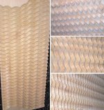
Maybe you've got a picture kicking around of the CNC machined wave pattern that we used in the second iteration of the A126 horn's "chamber"
Greets!
Hmm, being 'old school', I don't see how a realistic sized BLH can have a compression chamber (CC) since there's not enough counterbalancing acoustic load on the other side of the diaphragm. The front chamber of a compression loaded horn, ergo the rear chamber of a BLH, is an acoustic capacitance (Vb) in parallel with an acoustic inertance (St), IOW an acoustic low pass filter that shunts out the highs from entering the throat (St) and why for max BW in a FLH, none is used.
That said, if the filter chamber is sized as if it's a CC and the horn expands at a slow enough rate and terminates into an acoustically large enough mouth, then it will damp the driver so well that it's a moot point, basically making it an acoustic resistor, i.e. true transient perfect horn.
WRT air density, how is it going to be greater inside the filter chamber on average? I mean the air gets heated up to some extent, but this causes a drop in air density.
GM
Greets!
Sorry 'bout that!") I guess I watched too many Mr. Wizard shows when I should have been out playing cowboys n' Indians.
I guess I watched too many Mr. Wizard shows when I should have been out playing cowboys n' Indians.
For sure there's some pressure changes in the filter chamber as the driver causes compression/rarefaction wave action, though IIRC Ron E. 'did the math' on the old basslist and it wasn't much with a long throw sub, so a FR driver would be much less and one reason why the horn damps it so much. Of course you're right about the high to low pressure change between the horn's throat and mouth due to the change in area.
GM
Sorry 'bout that!
I guess I watched too many Mr. Wizard shows when I should have been out playing cowboys n' Indians. For sure there's some pressure changes in the filter chamber as the driver causes compression/rarefaction wave action, though IIRC Ron E. 'did the math' on the old basslist and it wasn't much with a long throw sub, so a FR driver would be much less and one reason why the horn damps it so much. Of course you're right about the high to low pressure change between the horn's throat and mouth due to the change in area.
GM

- Status
- This old topic is closed. If you want to reopen this topic, contact a moderator using the "Report Post" button.
- Home
- Loudspeakers
- Full Range
- The Frugel-Horn Project