Now I am the one that is confused. As I said, the design parameters were already set by Hamlet Mk2 and will match that, and I can assure you that the power response is just fine. I am not an armchair designer, I deal with the real world in a practical and even in a pragmatic way if need be. I am not a theorist, only somebody over many years has figured certain things out and that I get the results I want. And get them too.
"Power Response is the sum of the total radiated acoustic output of a loudspeaker as measured in a sphere around the speaker at several incremental intervals on- and off-axis in the far (reverberant) field."
Hence I have said to many, including notable speaker designers, that a speaker has many frequency responses, change the position of the microphone and you change the frequency response. But a speaker only has one power response and the above definition bears this out.
But it was you that brought up lobing affecting power response and you included the crossover. I have already sorted that out as I explained and detailed it too.
One of the reasons I avoid Butterworth crossovers is the lobing and the fact that you don't get 100% vector summing between drivers. I have written extensively about this 90-degree phase shift that only gives you 3dB and not 6dB (full summing) on my website. It wrecks the power response.
Maybe you have not come across that article? I don't always use MTM arrays and I don't so-called D'Apollito array either, even if they share the same MTM positioning of drivers. They just to me are not correct. I am one of only two people that have computer modelled the Duntech Sovereigns (I have a connection with Duntech since it came to Sydney) and can tell you all the flaws and why I would not have designed them that way. Go off-axis and you will see so many problems and evidence of lobing and how it has poor power response.
I suppose I have gotten to lengths in the above two msgs that I consider the power response paramount and that includes lobing/crossover etc.
PS: It is interesting that John Atkinson of Stereophile uses a 50 degree arc averaged out and publishes that as the frequency response. I like that because you also get a good idea if the power response is good too. If there is a lack of energy at the crossover point to the tweeter, a classic sign, even if it is not there on axis, it is still negatively heard.
Last edited:
Wow, Joe. Just wow.
AS someone who's built the Elsinores, and my brother has Dunlavy speakers, Mark Levinson amps, PS audio power conditioners, etc...It's kind of like trying to explain color to a blind person!
This reminds me of one time when I was a kid, a teenager. My father was color blind, born in 1927. We were at a traffic light, and the light went from a green Circle, to a RED ARROW. This was at a time when they were just going to colored arrows. My father could not see RED! He thought the arrow was GREEN, so he went. My younger brother and me, and our Mom, all told him, he ran a red light.
He was so mad he went back to the light, pulled over, waited for the light to change, and screamed at us asking what color the light was. (It was the maddest I ever saw him. He never cussed, but he did that day.) But my Dad, he humbly accepted the light was red! Even after his temper tantrum.
So here's my advice about what Joe Rasmussen is doing. You cannot see GREEN! All my Dad saw was RED! He saw a "red arrow" and thought it was green, because it was an arrow!

Upgrading Elsinore Crossover Components
I have had my Mark 6 Elsinores for a few years now and I am very pleased with them. Joe R built the crossovers for me. I have just revamped the crosovers by rebuilding them with "fancier" components.
Firstly I replaced all the wire wound resistors with 10W Duelund CAST Resistors
I replaced C1, the 1.8uF cap, with a Duelund JDM Tinned Copper Foil Capacitor
All the existing inductors that were iron core I replaced with air core types. Finally I replaced the MDL bi-polar caps with Mundorf ECap AC PLAIN capacitors.
And the result? I was surprised, my subjective observations were that I heard an overall improvement in clarity and transparency.
The bass had the most improvement being better defined and perhaps even slightly louder.
Just my $0.02")
Steve
I have had my Mark 6 Elsinores for a few years now and I am very pleased with them. Joe R built the crossovers for me. I have just revamped the crosovers by rebuilding them with "fancier" components.
Firstly I replaced all the wire wound resistors with 10W Duelund CAST Resistors
I replaced C1, the 1.8uF cap, with a Duelund JDM Tinned Copper Foil Capacitor
All the existing inductors that were iron core I replaced with air core types. Finally I replaced the MDL bi-polar caps with Mundorf ECap AC PLAIN capacitors.
And the result? I was surprised, my subjective observations were that I heard an overall improvement in clarity and transparency.
The bass had the most improvement being better defined and perhaps even slightly louder.
Just my $0.02
Steve
Last edited:
You should see a boost in the bass.
The increased resistance of your new coils will slightly increase Qt, a good thing with low Qt drivers.
The box tuning is forgiving enough to enjoy the change without requiring modification.
Our rooms are all different, this has helped you, my brother has a boomy room, we changed out air-core for lam-core in his speakers, it helped cut the amount of EQ he needed to deal with the worst room mode.
So, a useful tool either way.
Good work.
Last edited:
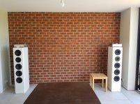
Great! Maybe some pics of your Masterpiece?
Here they are. More furnishings needed... One day they'll be reunited with the TV once I move to Finland.
Cheers
Attachments
.... where Red in On Axis (not recommended for listening), .....
Is that the same amount of 'not recommended for listening' that any speaker that is best not toed in towards the listening position would have?
I don't have a dedicated listening area and sometimes end up sitting directly in line with one of the speakers. Would that just not be optimum or would it be annoying?
Update:
PC Board has been ordered.
Are you going to sell the PCB's? If so can it ship with the waveguides?
Thanks for the discussion of the PCB over this past week Joe. However now, due to the nature of the product would you please create a vendors thread for continuing discussion (Note 5 & 6)PC Board has been ordered.

Thanks for the discussion of the PCB over this past week Joe. However now, due to the nature of the product would you please create a vendors thread for continuing discussion (Note 5 & 6)
I should have added that it was a Hamlet update. They need to know that I need the PCB to finish it and that means a delay. But getting there.
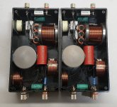
I could hardwire the crossover right now, I could get what I need almost overnight. But getting the PCB will take a bit more time.
I have a good reason to switch to PCB when I had to make five pairs of crossovers, see pic below. That doesn't even show the wires (12) plus banana connectors (24) and it was too much. PCB is the way to go, now up to where it goes.
But thanks for reminding me about a vendors thread. I am getting the PCB primarily for above reason.
Attachments
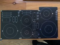
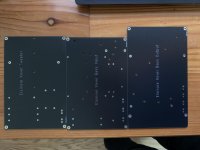
It's funny, I just ordered some PCBs meant for the Elsinore as well - though I took a different approach and choose to use larger air-core inductors. The results just got in today, and so far the boards don't look half bad.
My approach was to layer 3 boards on top of one another so they could fit into a box similar to this one or simply be placed in the bottom of the speaker. The two smaller boards are 180x120mm and the larger on is 200x120mm
My approach was to layer 3 boards on top of one another so they could fit into a box similar to this one or simply be placed in the bottom of the speaker. The two smaller boards are 180x120mm and the larger on is 200x120mm
Attachments
It's funny, I just ordered some PCBs meant for the Elsinore as well - though I took a different approach and choose to use larger air-core inductors...
I am also sourcing some 18mH inductors that are less massive and half the weight. There is no need to a low DC resistance inductor since it is already in series with a resistor in an LCR network. The inductor I am sourcing is 18mH and DCR is high at 3.2R, that means the series resistor value needs to be lower and I am thinking 3R9 10W would work, it means the total will be 7.1R (7R is the target) DCR and perfect. It is a quality inductor and made by Jantzen. Will I make those available with PCB, I am yet to decide but very possible.
Please note I am mainly getting this done for myself, but then open to help others. If I do decide, I will do as Allen says and start a new thread in the vendor's area. We shall see, but the more I think about it, it looks like this is where it is going.
BTW, it seems that you have to order this smaller inductor in quantity, this is what I am doing.
Neat! Curious to see how the final boards turn out, making this inductor available would probably be helpful, given that large value inductors seem to be difficult to procure (took me 2 months of waiting).I am also sourcing some 18mH inductors that are less massive and half the weight. There is no need to a low DC resistance inductor since it is already in series with a resistor in an LCR network. The inductor I am sourcing is 18mH and DCR is high at 3.2R, that means the series resistor value needs to be lower and I am thinking 3R9 10W would work, it means the total will be 7.1R (7R is the target) DCR and perfect. It is a quality inductor and made by Jantzen. Will I make those available with PCB, I am yet to decide but very possible.
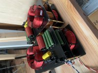
I just finished assembling mine... and they are heavy, roughly 10lbs a piece.
Attachments
- Home
- Loudspeakers
- Multi-Way
- The "Elsinore Project" Thread