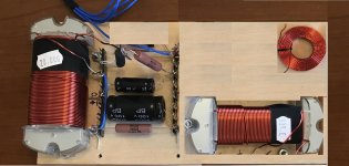
Try to rearrange the inductors so that they are perpendicular to each other. As it is, you will get a lot if crosstalk between them.Finally making some progress on my Elsinores. Crossovers finished today and only one coat of paint left!")
Try to rearrange the inductors so that they are perpendicular to each other. As it is, you will get a lot if crosstalk between them.
Thanks for the input and tip! Unless it's obvious, the two boards for each speaker will not be close to each other, so I assume you're talking about the two magnetic core and tiny air core inductors on the boards in the top of the picture. For some reason I had thought that I had read that the magnetic core inductors wouldn't be a problem in the current config. Should one of these be perpendicular to the other? May have to rethink this as there won't be enough room at the base of the speaker where I was going to attach this board.
That's a good catch by mbrennwa.
tompa909,
Here you go with a mock up of what mbrennwa is suggesting if I have understood correctly.
I have taken the liberty to elongate your XO board - hope that will still allow for suitable placement.
Others please chime in.
tompa909,
Here you go with a mock up of what mbrennwa is suggesting if I have understood correctly.
I have taken the liberty to elongate your XO board - hope that will still allow for suitable placement.
Others please chime in.
Attachments
Yes. Placement of coils in crossover networks
Scroll down to coil placement....
Scroll down to coil placement....
Scroll down to coil placement....
Taking another look at the Troels coil placement picture in the link above. The two larger inductors on my board are around 14cm apart so it seems that I'm somewhere between the 1st and 2nd image (somewhere between problematic and good). Maybe if I push them out another few cm to the edge of the board and I'll be ok?
Want a tip to know how to do it?
1/Just remember to never get their axial line to cross together and you're good (this is ensures that mag flux from one coil never enters the other coil's winding).
2/ keep them 10cm+ apart (this is for leaking flux of one coil to be really weak when reaching the other coil...)
1/Just remember to never get their axial line to cross together and you're good (this is ensures that mag flux from one coil never enters the other coil's winding).
2/ keep them 10cm+ apart (this is for leaking flux of one coil to be really weak when reaching the other coil...)
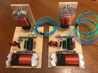
Thanks everyone for your very helpful comments. I have rearranged the layout and I think I'm no longer disobeying any of the inductor placement rules (fingers crossed).
I bought a multimeter with inductance capabilities out of curiosity and measured a 0.5mH increase measuring the two large inductors in series (note: they are not actually in series in the actual circuit, but this seemed to be the best way to measure the impact of changing the orientation of the inductors).
Assuming nothing goes wrong I should have the speakers up and ready this weekend!
Attachments
I have rearranged the layout and I think I'm no longer disobeying any of the inductor placement rules (fingers crossed).
Ehmm... I think you still have at one place: magnetic coupling could be made weaker between the front inductor and the small round one standing on its side at the left on the picture... but I may be picky about its effect here...
Regards,
Kal
Thanks everyone for your very helpful comments. I have rearranged the layout and I think I'm no longer disobeying any of the inductor placement rules (fingers crossed).
Looks good to me!
Ehmm... I think you still have at one place: magnetic coupling could be made weaker between the front inductor and the small round one standing on its side at the left on the picture... but I may be picky about its effect here...
Regards,
Kal

Last edited:
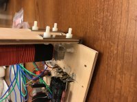
Ah, I never thought of the screws! 
No more metal screws, replaced with nylon screws. Speaking of metal, I may now have another problem. The corner brackets that are holding the inductor vertical. According to the packaging they are made out of zinc. Do I need to cut off an inch or so of the bracket?
No more metal screws, replaced with nylon screws. Speaking of metal, I may now have another problem. The corner brackets that are holding the inductor vertical. According to the packaging they are made out of zinc. Do I need to cut off an inch or so of the bracket?
Attachments
..Speaking of metal, I may now have another problem. The corner brackets that are holding the inductor vertical. According to the packaging they are made out of zinc. Do I need to cut off an inch or so of the bracket?
Chances are they are Zinc PLATED. So again, likely steel. (..basically a poor man's stainless steel because Zinc is a rust inhibitor.)
It really depends on the amount of interaction.. same for the screws, but note that the plates are further from the inductor and behind the hdf board, not right up against the inductor like the screws were.
Also the little Inductor just needs to be turned 90 degrees.
One other thing:
..are you sure you have enough resistance for the signal portion of the midbass driver's with that large iron-core inductor? (..relative to the design.)
I'm also a little wary of the added hysteresis that the iron core generates..Here are the components in-place that I spec'ed for Pilk (..it's a fairly *expensive result, but in-keeping with the quality of the loudspeaker's design):
https://www.diyaudio.com/forums/multi-way/97043-elsinore-project-thread-270.html#post6085312
*the loudspeaker's design is overall excellent, and premium components in the right area of the crossover can make a noticeable difference (provided other equipment is also good). While the crossover here is expensive, I really tried to maximize "bang for the buck", so many of the parts costs are comparatively moderate (..and the most crucial (IMO the tweeter's resistor) was half-price at the time it was purchased).
Note I'm not particularly fond of the screw-down terminals on Pilk's boards - and would have much preferred "flying-leads" (wire extension). That 1mH air-core foil inductor in particular has it's "core" facing 2 screws, which is something that bother's me a little bit and can be replaced by copper screws. (..and hopefully the terminal's "block" is solid copper.)
Last edited:
Also the little Inductor just needs to be turned 90 degrees.
One other thing:
..are you sure you have enough resistance for the signal portion of the midbass driver's with that large iron-core inductor? (..relative to the design.)
Thanks Scott,
If I turn the little inductor isn't it going to be the same direction as the 20mH iron-core and that's the reason I turned the 4mH vertical?
In terms of resistance, yes, the resistance of the 20mH inductor plus the 6R8 resistor add up to 7.5Ohm as per Joe's recommendation.
The parts you spec'ed for Pilk are definitely very nice. I was trying to maintain a budget friendly crossover for now.
- Home
- Loudspeakers
- Multi-Way
- The "Elsinore Project" Thread