Hi Joe, did you ever go any further on investigating the possibility of a MW16P-8 Satori version of the Elsinore?
Yes, it was looked at. It would likely work, but would it be better? The box tuning also looks like it should not be a problem.
The big issue is the time it would take and the cost of the drivers also means/asks the question, how many will do this version over the current EL-6?
So it is not a priority right now. Also, there is something about the design used here, and I am reluctant to get into too much theory here as that has been tried before on other forums and it did not go too well. I am writing a paper on the subject and it has to do that all power amplifiers are essentially "current delivery systems" and that we are listening to the current of the amplifier rather than its voltage. For some reason, some see red at that point being made. But measurements are being developed that will support this, some of these have already been done and submitted to people of high repute (several are physicists, actually three of them) who would not hesitate to set me straight if I go of the true path of actual science. Measurements of distortion, fully documented in such a way that any proficient person can duplicate them, that is the only way to go forward. The Elsinores are based on this and as one very experienced friend (another scientist) said after listening to the Elsinores, that they were the lowest distortion speaker that he had ever heard. Might be able soon to prove something about that.
The Elsinores, by drawing the same amount of current from the amplifier at all frequencies, suppress current distortion of the amplifier. We already have measurements that proves that and more are coming and looking really good.
But based on this, going over to the more expensive driver may actually have less benefit that what you might think.
As I said, many will view this as controversial, but shouldn't be, just because the topic is a difficult one.
I am reminded by Richard Feynman's words:
"There is pleasure in recognising old things from a new viewpoint."
Cheers, Joe
.
We already have measurements that proves that and more are coming and looking really good.
Joe your tenacity is admirable, any chance that you would post these. Not holding my breath.
I'd like to know what improvement I might expect by replacing the Peerless midbass drivers with SB drivers. I have MK5's built 9 years ago which I'm very happy with but if I knew there was significant improvements to be had I'd upgrade to SB drivers. Anyone done an AB comparison?
Joe your tenacity is admirable, any chance that you would post these. Not holding my breath.
Hi Scott
But I now understand you now have an interest and I appreciate that.
But a single measurement or two here, without an exact context, is not helpful. It could even be misleading.
For example, have you seen Pavel's (PMA) measurements on his website?
Link: Current drive of speakers and speaker distortion
These are indeed distortion measurements (a bit crude since his 1R current sense value is way to high and I use 100mR and potentially 20dB more resolution). He made the conclusion that the driver is more linear under current drive. Esa Merelainen has also made a similar conclusion. It is understandable, but also wrong. The measured distortion across the current sense resistor is the amplifier's current distortion. Think about that for a moment... but I had to find a fool proof method rather more sophisticated than what they have done, in order to prove it. And I did.
So I am only going to publish when the boat fully floats. Or else others are sure to sink it.
What is interesting is that I can now explain LF effects that Esa has not been able to and even able to do it mathematically. By defining the current versus frequency I have some surprises in store. By manipulating the current in the voice coil I can change the Q of the drive at LF of a sealed box. I have shown this to a handful of people and the way it is done is deceptively simple and should have been obvious. But the way it works is into a much larger scheme and becomes very powerful proof: Choose any frequency and the output dB-SPL is always proportional to the current relative to the current and dB-SPL of any other frequency.
You will get the results and more, I promise. A full 3D explanation where it can be examined from multiple angles.
But this forum here is not the place, this is for Elsinore builders (I wish you could hear a pair of them) who basically look after each other. I have a friend well loved in EU audio circles, with whom I have discussed that he moderate a Facebook forum for invitees only. It will get a fair shake there and greater exposure afterwards. Even before then it will have some high powered scrutiny first, it will have to be sink proof or else you will just get silence from me. And I have to live a little longer, none of us are getting younger and family 'illness' is a drag on time too.
Cheers, Joe
He made the conclusion that the driver is more linear under current drive.
This of course has nothing to do with the contentious discussions of the past.
You're fully right to me, Joe: no passionate belief or secret here for anyone at ease with physics, and I believe there are many among the forums
No will to revive an old debate...
It's actually simple, from the standpoint of applied physics into a loudspeaker driver, bear with me:
Sound is membrane motion=>
Membrane motion is caused by the coil moving the membrane=>
Coil moves according a force which builds up and is applied to its wire=>
(yes, the actual mechanical source of force into the driver is the coil wire)
This force is generated by the CURRENT flowing into the coil, when changing over time -the music modulation- by the fact this current flows while placed into the steady magnetic field of the magnet.
Please note: formulas describing the moving force that builds-up at any moment in time and applies to the coil wire do not make use of the coil voltage in any way, only the coil current...no secret here.
regards,
Kal
Hi Kal
Hi Kal
You have some plain insight, the best kind.
True.
True.
True.
True.
Absolutely true.
But may I also add this: Any change in current will give you a proportional change in the dB-SPL of the driver at that frequency. Choose another frequency, and it will be true for that frequency as well. The output might be different, but the proportionality of change is the same.
If you think about that, it means that any distortion measured on the current side of the amplifier, that is not present on the voltage side (usually low distortion), then it is the higher distortion on the current side that you are listening to.
Hang on, have we just described a situation where the amplifier has two different distortion profiles, one on the voltage side (low distortion) and another on the current side (rather higher distortion)?
*Yes.
[*See PS below.)
The only time the two will have the same distortion profile is when the load is resistive. As soon as the driver is connected, you end up with two distortion profiles. Now we need to explain that, and that is what I will be doing. In 1961 Neville Thiele (I am in his city of Sydney, just up the road in the Sydney University where Thiele Parameters came into being), he did something that proves that a voltage source can become an actual impedance. In that fact there is an explanation as to why that current distortion profile shows up with the driver being anything other than resistance. So there is nothing new here, but there sure are things that needs to be clarified.
Also, since I can (and it will be revealed how) I can also the Q of a sealed box alignment from Butterworth (0.71) to a more damped Bessel (0.56) by simply manipulating the current versus frequency at LF, so that under voltage drive it is a Butterworth, but under current drive it becomes a Bessel alignment. Yes, increased damping from current drive? Yes. Like many things about current which are less than intuitive, this just sounds way too strange and the trolls will not try to understand. But the explanation is oh so simple, once you have been shown how it works. Trust me, you will definitely understand it, because you have attempted to understand what the current in the coil does (and yet, the force of movement is on the current in its relationship to the gap).
That the Q of a system can be changed by manipulating current versus frequency, I am speaking to mathematicians and see if they can come up with a mathematical equation that reflects/explains it. That thought is very exciting.
Cheers, Joe
*PS: The link I showed earlier shows that somebody else has already proved that fact with distortion measurements. Pavel Mecura (PMA) did it first and I tried to point out to him the significance. Alas, I got a cold shoulder, but I still credit him.
Link: Current drive of speakers and speaker distortion
Hi Kal
You have some plain insight, the best kind.
Kalamin said:Sound is membrane motion=>
True.
Membrane motion is caused by the coil moving the membrane=>
True.
Coil moves according a force which builds up and is applied to its wire=> (yes, the actual mechanical source of force into the driver is the coil wire)
True.
This force is generated by the CURRENT flowing into the coil, when changing over time -the music modulation- by the fact this current flows while placed into the steady magnetic field of the magnet.
True.
Please note: formulas describing the moving force that builds-up at any moment in time and applies to the coil wire do not make use of the coil voltage in any way, only the coil current...no secret here.
Absolutely true.
But may I also add this: Any change in current will give you a proportional change in the dB-SPL of the driver at that frequency. Choose another frequency, and it will be true for that frequency as well. The output might be different, but the proportionality of change is the same.
If you think about that, it means that any distortion measured on the current side of the amplifier, that is not present on the voltage side (usually low distortion), then it is the higher distortion on the current side that you are listening to.
Hang on, have we just described a situation where the amplifier has two different distortion profiles, one on the voltage side (low distortion) and another on the current side (rather higher distortion)?
*Yes.
[*See PS below.)
The only time the two will have the same distortion profile is when the load is resistive. As soon as the driver is connected, you end up with two distortion profiles. Now we need to explain that, and that is what I will be doing. In 1961 Neville Thiele (I am in his city of Sydney, just up the road in the Sydney University where Thiele Parameters came into being), he did something that proves that a voltage source can become an actual impedance. In that fact there is an explanation as to why that current distortion profile shows up with the driver being anything other than resistance. So there is nothing new here, but there sure are things that needs to be clarified.
Also, since I can (and it will be revealed how) I can also the Q of a sealed box alignment from Butterworth (0.71) to a more damped Bessel (0.56) by simply manipulating the current versus frequency at LF, so that under voltage drive it is a Butterworth, but under current drive it becomes a Bessel alignment. Yes, increased damping from current drive? Yes. Like many things about current which are less than intuitive, this just sounds way too strange and the trolls will not try to understand. But the explanation is oh so simple, once you have been shown how it works. Trust me, you will definitely understand it, because you have attempted to understand what the current in the coil does (and yet, the force of movement is on the current in its relationship to the gap).
That the Q of a system can be changed by manipulating current versus frequency, I am speaking to mathematicians and see if they can come up with a mathematical equation that reflects/explains it. That thought is very exciting.
Cheers, Joe
*PS: The link I showed earlier shows that somebody else has already proved that fact with distortion measurements. Pavel Mecura (PMA) did it first and I tried to point out to him the significance. Alas, I got a cold shoulder, but I still credit him.
Link: Current drive of speakers and speaker distortion
Last edited:
That reminds me of something Marcus Aurelius once said.
So I thought I'd demonstrate how to do this.
..that with just an equaliser/signal processor one can achieve this with a speaker by adjusting the response. Siegfried Linkwitz among others had a lot to say on the subject.
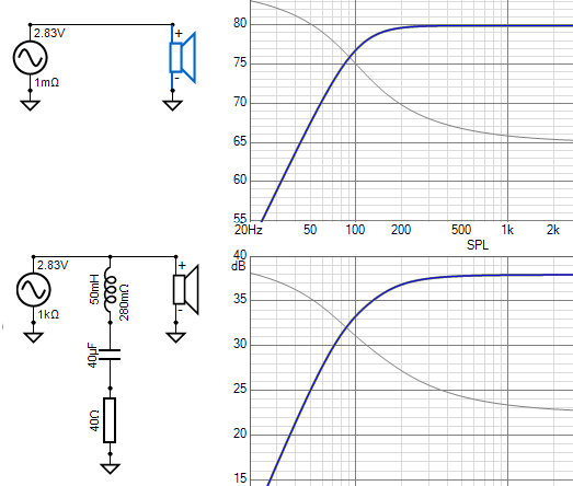
Unfortunately there looks to be a glitch in applying Pavel's current distortion tests here.
So I thought I'd demonstrate how to do this.
..and the excercise revealed something interesting.(and it will be revealed how) I can also the Q of a sealed box alignment from Butterworth (0.71) to a more damped Bessel (0.56)
..that with just an equaliser/signal processor one can achieve this with a speaker by adjusting the response. Siegfried Linkwitz among others had a lot to say on the subject.
Unfortunately there looks to be a glitch in applying Pavel's current distortion tests here.
Attachments
You have my admiration.
Some quick thoughts.
1. It is the 1K that makes the difference... it happens to be the same value of a current source used by Neville Thiele, measure the Re and the voltage across the driver and plotting the LF Z and hence the alignment could be calculated when fitted into boxes of different sizes. The added LCR you show (get the values just right), now affects the current versus frequency because the current of the source is effectively fixed within a few percent. The alignment is a function of current versus frequency. Do the maths and why it is near -5dB at Fc and at half-octave it is -14dB instead of -12dB because by then it has become a fully developed 2nd order. Anything above the Re value is a voltage source and here it becomes an impedance, yes, voltage becomes a back-EMF impedance. It all fits together and I have even done the maths and it was accepted by Dr. Rod Crawford who could not fault it. I think even Scott Wurcer here might think it is at least near the mark?
"Back EMF has been known for almost 100 years now. It can be shown that as far as the amp is concerned the back EMF simply looks like a complex impedance and... There simply is no difference between back-EMF and impedance." Earl Geddes in a PM to myself.
Yet Earl disagrees with me, and yet he agrees with me at the same time? It is very perplexing. I have been 'corrected' for using the phrase "back-EMF impedance" and yet he uses it himself in a PM. Very curious.
2. You know what that does to any theory attached to amplifier's having a 'damping factor' and as to whether it is a Butterworth or Bessel? I can tell you, Richard Small taught me that it is the alignment that determines the damping entirely and not the output impedance. He and Thiele disliked any theory of the amplifier as having 'damping factor' and even Small said it irritated him.
3. Pavel's effort may leave something to be desired, but he made an effort. I just wish he would have engaged with me differently when I approached him. Instead he treated me like, what can I say, as a flake? That I just don't get and if he reads this and has changed his mind, I will forget the past and look to the future. In the last 5-10 years there has been things slowly happening on this subject and the future will win.
4. I also credit Esa's book, I was one of the first to get a copy. Even if there too I believe he has made some incorrect conclusions. I think some very unkind things have been said about him too. Like some saying that he has been "debunked" and that is not the case at all.
But we live in interesting times, on multiple levels!
Cheers, Joe
.
Last edited:
Yes h3, h5 etc. distortion components drop considerably with current drive even if the driver has copper shorting ring and very low Le. Easy to test with a series resistor. Also measuring with an SE tube amp (at low levels) they are always little lower than with voltage source drive.
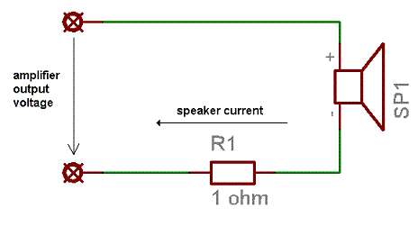
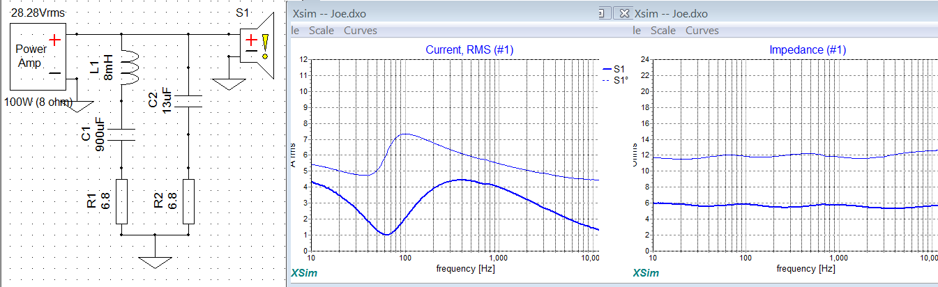
That impedance smoothing rlc cannot be used Im afraid, it will negate the effect of current drive (look at the loopback impedance, which has to be high). If you put a 8ohm resistor across the driver's terminals, the net "drive impedance" is 8ohms, not 1k (= limits the effect of current drive to equivalent of 8ohm series res/output imp.).
The impedance has to be made flat with an aperiodic enclosure for the full effect, at least this is my impression. Been using strategical current drive (for ex. favor series res attenuation, not l-pad) for many years. Once had a fullrange drivers with considerable amount of current drive in a form of 50-100ohm series res + step-up transformers to bring the sensitivity back up. The effect to h3, h5 was quite dramatic. H2 can be higher near the Fs, but H2 in of no importance SQ wise.
That impedance smoothing rlc cannot be used Im afraid, it will negate the effect of current drive (look at the loopback impedance, which has to be high). If you put a 8ohm resistor across the driver's terminals, the net "drive impedance" is 8ohms, not 1k (= limits the effect of current drive to equivalent of 8ohm series res/output imp.).
The impedance has to be made flat with an aperiodic enclosure for the full effect, at least this is my impression. Been using strategical current drive (for ex. favor series res attenuation, not l-pad) for many years. Once had a fullrange drivers with considerable amount of current drive in a form of 50-100ohm series res + step-up transformers to bring the sensitivity back up.
The effect to h3, h5 was quite dramatic. H2 can be higher near the Fs, but H2 in of no importance SQ wise.
Last edited:
Thanks Joe. I find it curious that Earl Geddes would say that.
It's a while back, water under the bridge. But at least he confirmed the most important bit, that back-EMF (voltage) can be an impedance. That is good enough for me.
scottjoplin said:Acoustic distortion measurements would settle this old repetitious argument, but then that would defeat the object, probably many more years to wait.
Good things comes to those who are patient. Acoustic measurements done and more to come (you will be surprised), but you won't get to see them here. This is not be the forum. As for repetitious, not at all. Only to those too quick to be dismissive and who has no interest. Is that a good and fair description of the attitude you have decided to take, based on this and past posts? Only you can say.
Cheers, Joe
.
That impedance smoothing rlc cannot be used Im afraid, it will negate the effect of current drive...
This view I believe is not quite correct, indeed it may well disguise an understanding of something else going on. But I do understand and appreciate the argument and indeed would have agreed in the past. This is also Esa's view. But my view has changed, even if what you say contains an element of truth.
I won't go into detail here. This is for DIY building of Elsinores and for those guys helping each other out - I try to be low key and do my bit to help. Theory is for another place.
Cheers, Joe
.
 NOT ALLOWED
But at least he confirmed the most important bit, that back-EMF (voltage) can be an impedance. That is good enough for me.
The units don't match, that's physics 101. The units of impedance are not volts they're Ohms (acoustical or electrical).
Yet Thiele demonstrated in his 1961 paper otherwise, voltage = impedance and used that fact to measure the impedance of a raw driver. I am on solid ground. Even Earle has agreed, even if there are other aspects where we are yet to agree on. That's OK too. But the back-EMF of a driver exert an impeding of the current in the voice coil. It's so basic I am surprised why I should even have to defend it. Why? The back-EMF impedance is the total impedance at any chosen frequency minus the DC resistance of the voice coil. Both maths and measurements are in place.
I'll go back to ignoring these threads, you have an amazing resistance to getting a grasp of the very basic definitions (for years). Electrical impedance | physics | Britannica
You heard impedance = volts in your imagination.
The magnitude of the impedance Z of a circuit is equal to the maximum value of the potential difference, or voltage, V (volts) across the circuit, divided by the maximum value of the current I (amperes) through the circuit, or simply Z = V/I. The unit of impedance, like that of resistance, is the ohm.
You heard impedance = volts in your imagination.
Last edited:
- Home
- Loudspeakers
- Multi-Way
- The "Elsinore Project" Thread