luvdunhill said:
what's that? what's the output look like into a 100pF load?
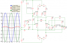
"That" is me playing with a couple of transistors and chokes. I wanted to see how far I could go with voltage gain and still maintain a decent looking sine-wave...
As far as the 100pF goes, I'll load it into the sim and see.
I coupled a 100pF cap to each output and took them to ground. There is no effect on the sine-wave.
BTW, I discovered that the positive rail doesn't require more than 15 volts. It's the bottom (negative) rail that wants voltage. It's scalable--just don't input as much voltage and the output is happy. I just ran it with 30 volt negative rails and it looks great with two volts input.
BTW, I discovered that the positive rail doesn't require more than 15 volts. It's the bottom (negative) rail that wants voltage. It's scalable--just don't input as much voltage and the output is happy. I just ran it with 30 volt negative rails and it looks great with two volts input.


http://www.diyaudio.com/forums/attachment.php?s=&postid=1486025&stamp=1208376110
Within short time, i have one channel good for testing, but could some explain howto adjust the thing. ?
I suppose, as it look''s like the that attennuation, should be at input ?, and that R6/R7, R18/R21 forms the gain of the circuit. ?
I also suppose that both +in and -in must be shorted to GND (or attennuator at zero - thanks ZenMod for those lessons btw.. back when we did  ) ... , and that i have to make a ''jumper'' to connect pgnd and sgnd ?
Jesper.
Within short time, i have one channel good for testing, but could some explain howto adjust the thing. ?
I suppose, as it look''s like the
that attennuation, should be at input ?, and that R6/R7, R18/R21 forms the gain of the circuit. ?I also suppose that both +in and -in must be shorted to GND (or attennuator at zero - thanks ZenMod for those lessons btw.. back when we did
) ... , and that i have to make a ''jumper'' to connect pgnd and sgnd ?Jesper.
lykkedk said:http://www.diyaudio.com/forums/attachment.php?s=&postid=1486025&stamp=1208376110
Within short time, i have one channel good for testing, but could some explain howto adjust the thing. ?
I suppose, as it look''s like the
I also suppose that both +in and -in must be shorted to GND (or attennuator at zero - thanks ZenMod for those lessons btw.. back when we did
Jesper.
before powering up :
set R25 to max value
set both R5 and R11 to mid point (value ) if they aren't already
then ( after powering up) - adjust R25 to have 15 mA through center CCS , or 3V3 across R24
then set R5 to have 1V to 1V5 across R1
then set R11 to have same voltage across R17 , or - BETTER - to have 0V between drains of Q1 and Q6
all inputs grounded
pot on input
let beast cook for some time , then recheck settings with R5 and R11
I presume/resume that procedure is simple and self-explanatory

lykkedk said:Yep.. just what i needed...
Very good cook-book for non novices
Jesper.
Well, before you power it up, I want you to know that I am happy to have known you
Magura
Magura said:
Well, before you power it up, I want you to know that I am happy to have known you
Magura
Me too, see you on the other side
Lykke was one heck of a guy Magura said:I just had him on the phone
Maybe because he is still burning ?
jacco vermeulen said:
Maybe because he is still burning ?
I doubt it, no squealing was detected
Magura
Magura said:BTW, Jesper drop me your addy, and I'll send you a couple of those caps you lack.
Magura
better send him a Coppertone ........

Zen Mod said:
better send him a Coppertone ........
So you think he's gonna wear a pale white tan, once he gets it up and running, due to outrageous number of hours in the shed?
Magura
Magura said:
So you think he's gonna wear a pale white tan, once he gets it up and running, due to outrageous number of hours in the shed?
Magura
so - what lykkkkk sez - when he's gonna power up squib ?
- Status
- This old topic is closed. If you want to reopen this topic, contact a moderator using the "Report Post" button.
- Home
- Amplifiers
- Pass Labs
- The Drek builder's thread