1) Most portable meters have a lot of error when reading sub- 10ohm.
2) A 6 digit bench meter with Kelvin probes is a extremely useful tool and a wonderful luxury, but for this hobby is exactly that, a luxury...
3) Buy the parts you can get, put them in the circuit, and don't worry about it.
Matching to the nth degree, or not, is not going to make any audible difference either way, and is rarely measurable. I've built enough of the Pass DIY designs that I feel that I can safely recommend this.
I’ve had issues measuring the 3w Panasonic resistors with my DVM as well. I thought it might have to do with the length of the leads as well, since most of it gets trimmed off once soldered in. I’ll try a fresh battery too. Thanks for that tip. Ultimately I’m saving up for a nice Fluke meter though.
I have a fluke, but awfully expensive. Tenna makes some awfully good ones for a lot less. I use mine most often.
Russellc
1) Most portable meters have a lot of error when reading sub- 10ohm.
2) A 6 digit bench meter with Kelvin probes is a extremely useful tool and a wonderful luxury, but for this hobby is exactly that, a luxury...
3) Buy the parts you can get, put them in the circuit, and don't worry about it.
Matching to the nth degree, or not, is not going to make any audible difference either way, and is rarely measurable. I've built enough of the Pass DIY designs that I feel that I can safely recommend this.
I have to agree in practice, but some things I do for, as Zenmod says, "best sleep." LOL.
Russellc
Those who are unable or unwilling to measure their resistors, can read post #479. In which member 6L6 argues that Nelson Pass's M2 circuit design works beautifully even when the components are not painstakingly matched and super precisely measured. Adopting this philosophy will save you some time and, if you were considering buying a 5.5 digit precision DVM for $175, it will save you some money too.
Me personally? I already own a super precise "benchtop" (not handheld) multimeter; in fact I own two, that I bought used. And they have four-point-probe "Kelvin sensing" resistance measurement, as a built in & presupplied feature. They're not especially cheap, even used. Attached below is a representative listing, from linearz.com . But hey, it's my hobby, and I can spend as much or as little as I want to spend, on tools & equipment.
_
Whenever I have to use small value resistor, I usually parallel 1R resistors, in this case is 2 1R resistors. I think parallel is the way to go for high wattgate resistor, at least they have more "legs" to carry a current.
I have the feeling that my posts are frequently understood differently as how I originally intended them. English not being my main language is most likely the culprit, so I apologize.Those who are unable or unwilling to measure their resistors...
I was not mentioning unwillingness on my behalf or down-playing your suggestion of buying some extra and put on the most similarly matched.
I was just venting a minor frustration by he fact that my hobby tools are not able to reach that level, which I would have liked. Not to be precise to the femto-value, just to know things are as tight as budget and tools would allow. In my case, that would mean probably just installing them as is.
I did not intend any criticism nor was I trying to denote snobbism on those who do that, and certainly not any unwillingness to try or even buy into slightly more expensive items. That said, a US $175 DVM would cost here around $400, if you can find any, so it's not always laziness or unwillingness.
Sorry if this was not how my messsge came through,
Best regards,
Rafa.
With all the resistor measuring discussion, is just fell into oblivion. Can the brilliant minds here please share this info which I lack?Hey friends,
For the Ishikawa board, what would you recommend for the idss of the JFETs? More leaning towards the lower values (6.5 - 7.5), towards the middle (8 - 9) (which are much harder to get) or toward the upper values (9-10).
Perhaps I'll shoot myself in the foot and buy 2 full sets (for 2 NNPP type amps). I have yet to find 4x74s for the AlephJ.
Getting the parts is a bit of a treasure hunt!, isn't it? And then you go to the DIYStore and see "only two left" on the back panel parts kit and start to sweat! This is not a hobby for the undecided or slow buyers like me!
Thanks for bearing with me, best regards,
Rafa.
Thanks,
Rafa.
Mountain View and Tucson have relatively few solder joints and relatively few components to purchase. Each and every one of the components on both boards, is in production today, and is available from Mouser, DigiKey, Arrow, Avnet, Newark, Element14, RSComponents, and others.
The same is true of Austin and Norwood but they are more challenging to the "Help Me Obi Wan Kenobi" type of beginning kit builder. One is surface mount and the other is higher density.
The same is true of Austin and Norwood but they are more challenging to the "Help Me Obi Wan Kenobi" type of beginning kit builder. One is surface mount and the other is higher density.
For a small amount of builds, the price of a finer DVM may actually be more than purchasing into those $2 ~ $6 a piece for the 1% 3W resistors posted early? Has anyone tried those? NS02BR4700FE12 Vishay / Dale | Mouser
Thanks,
Rafa.
Yes NS serie Vishay 3 watt's is no inductive resistor version , leads are made with magnetic metal very good component anyways.
Vishay | Mills are the best Top Numero Uno audio resistor :
no inductive, no magnetic, can dissipate more heat 4 ~ 5 watt's at similar price :MRA-05R4700FE12 Vishay / Mills | Mouser Europe
Conrad get in stock Japan made Futaba MPC74 superb 0.47R source resistors cost less 1$
Metal film resistor 0.47 Ω Radial lead MPC74 5 W 5 % Fukushima Futaba MPC74 5W 0,47 Ohm 5% 1 pc(s) from Conrad Electronic UK
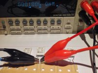
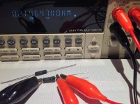
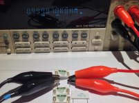
4 wires Kelvin test : Mills, Panasonic, MPC74, Caddock, Vishay NS-2B.
Conclusion yes Diyers match resistors is for perfectionist")
Conclusion yes Diyers match resistors is for perfectionist
Attachments
-
 6F763CD3-5F8F-4355-835B-FDAE0154E865.jpg354.5 KB · Views: 769
 -
 DF511EEE-8E47-4C53-9483-AAEA62B6D703.jpg411.7 KB · Views: 767
 -
 BDE0C9A0-D875-45AD-9D85-3B0BED8C43A7.jpg399.2 KB · Views: 751
 -
 FF97A95F-5AF9-4BB7-AEEF-4B4312A2F48D.jpg425.8 KB · Views: 734
 -
 3ACD4D0B-D255-465E-8212-407D957A6B8C.jpg430.4 KB · Views: 718
 -
 F4DAFAA1-2A6A-43BB-B56E-9795C93A349E.jpg235 KB · Views: 343
 -
 A8AE5569-5F69-49DA-A88D-B6FB07879849.jpg432.7 KB · Views: 289
 -
 F4F243AE-C85E-42E2-B57C-063634A90761.jpg431.1 KB · Views: 291
 -
 A1A032FD-7D27-468B-AAC4-8DEB602D9F94.jpg426.7 KB · Views: 273
 -
 0E5EA555-BDA9-4446-A2DB-2CE7D47D70C9.jpg428.4 KB · Views: 261
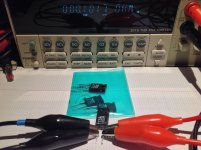
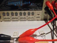
Another way to measure low resistance is supplying the resistor with a constant current source and check the voltage drop across the resistor.
If you feed a 0R47 resistor with for example 2A you´ll get 0,94V.
Easy to measure with a simple DVM.
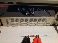
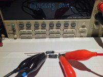
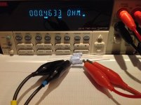
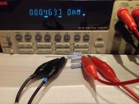
That is exactly what the 4-wire Kelvin measurement does. We have discussed it a few posts back, and that is what Soundhppy is demonstrating in the pictures.
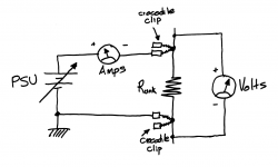
If you have two DVMs you don't even need a constant current source. Just use one DVM as an ammeter and the other DVM as a voltmeter. Write down both the current and the voltage in your lab notebook and then use Ohm's Law to compute
Resistance = Voltage / Current
The requirements placed upon the DVMs are not severe. Ammeter will read something around 500mA depending on how you set your PSU. Voltmeter will read something around 200mV to 400mV. Well within the ranges of even the cheapest Banggood / AliExpress / eBay DVMs.
Be sure to connect the voltmeter OUTSIDE the high current path, as shown.
_
Attachments
I have a fluke, but awfully expensive. Tenna makes some awfully good ones for a lot less. I use mine most often.
Russellc
Whoops, tenma.
Russellc
I'm note sure- can I use 15v PSU to measure 0.47R on this circuit?If you have two DVMs you don't even need a constant current source. Just use one DVM as an ammeter and the other DVM as a voltmeter. Write down both the current and the voltage in your lab notebook and then use Ohm's Law to compute
Resistance = Voltage / Current
The requirements placed upon the DVMs are not severe. Ammeter will read something around 500mA depending on how you set your PSU. Voltmeter will read something around 200mV to 400mV. Well within the ranges of even the cheapest Banggood / AliExpress / eBay DVMs.
Be sure to connect the voltmeter OUTSIDE the high current path, as shown.
_
The schematic in post #533 attempts to communicate that the PSU needs to have variable output voltage. That is why there is a diagonal arrow through the Voltage Source symbol on the schematic: the arrow means "Variable Voltage Source". You'll probably set your PSU for something like 0.4 volts and then twiddle its output voltage knob up and down, until the ammeter reads something like 500mA.
It's a lab power supply with variable output voltage. Something like this product .
But I have to add: for people who have difficulty with Ohm's Law and/or difficulty predicting the appropriate currents and voltages when measuring an 0.47 ohm 3 watt resistor: it's probably better and safer if you read and follow the advice from member 6L6 in post #479.
M2X board sets are now available from the diyAudio store. Photos and content will be updated in the next few days, but due to the delays I wanted to get this up and available for sale ASAP.
M2X – diyAudio Store
M2X – diyAudio Store
Great news!
Ok, I know I want these, and will be buying a set tomorrow so I dont get cut off again. The only question is: is there going to be a kit with the transformers? Or a transistors kit? (Without the Toshibas, of course)
If so, it would save me a lot in shipping, so I could wait for that. If it's not likely, I'll just buy this PCBs right away.
Thanks again,
Best regards,
Rafa.
Last edited:
- Home
- Amplifiers
- Pass Labs
- The diyAudio First Watt M2x