Baffle step is indeed tricky. So what I do in terms of simulation is create a few different woofer files with varying amounts of baffle step loss and then work out a xo for each case. Then I let my ear decide which one seems most accurate and enjoyable and adjust accordingly.
Sound confusing?
It's actually very simple thanks once again to Jeff B. Go back into Response Modeler and import your peerless file with the full 6dB of bsc. Now look at the screen grab below and notice what I've circled in red. This is a function that will adjust the baffle step loss either up or down.
In your case, you want to select "Inverted" and for a small speaker like yours, I would model 2 more cases - one with about 4.5dB of baffle step loss and another with 3dB. For those, select "% Steps" of about 19% and 41% respectively. Save each of those files, then extract minimum phase as usual and then try each one in PCD. For comparison, I've attached my results below (you'll need to change the file extension back to .frd).
I encourage you to go through this process starting with the full 6dB of loss and then moving on to the other 2 cases because, among other things, it will help you again to see how the baffle step is simply handled by the main woofer coil. You should also see that once you find an agreeable xo for the 6dB situation, you can keep the same topology for the other cases but just need to make small changes to a few components.
Btw, an LCR will indeed work on your woofer's 4500Hz peak but a single tanking cap added to the main inductor will do the same job with just 1 component. Again, you've got to play around with it in PCD to see how easily it works.
jReave, I am overwhelmed by the length that you took to help me out. I learned so much in last few days. You and wintermute gave me many practical suggestions that I can play with.
Now, I just need to figure out a way to tell my wife why I need another $80 order to Parts Express or Madisound. (I am building 4 of these bookshelfs. 2 with the RS28A-4. 2 with the Vifa D27TG-35-06.)
Troels Gravesen had something very interesting to say with his frankly unsatisfactory Nomex 830875 2.5 way project.
I did a little research before settling on the Nomex. I was able to get a pair of the 830875 for less than $100 2 years ago when I made that decision.
I found that I have to jump to $300 a pair to find significant improvement in performance. It finally became a value per cost decision.
What would be a good upgrade at the under $120 a pair price point?
You'll find that the response is the target. For example.. say you deal with the upper response of a midrange driver by using RC impedance rise compensation and a series inductor, plus a notch filter around breakup. Then you find you can achieve the same response/phase with just a second order filter with a resistor in series with the capacitor for adjustment. Parasitics aside, they should sound the same.What is the most practical crossover topology to effect the partial baffle step compensation that gives me the best chance of the right sound?
By and large in a case like yours where the baffle step winds up near the middle of a driver's passband, the upper response wants to be at the right level and to go with the crossover. The right level depends of course on how you deal with the region below.
..
Morning Sreten.
Now, I just need to figure out a way to tell my wife why I need another $80 order to Parts Express or Madisound. (I am building 4 of these bookshelfs. 2 with the RS28A-4. 2 with the Vifa D27TG-35-06.)
Hold off on that for a little while
") Another of Jeff's spreadsheets (which I've only had a rudimentary play with) is his Baffle Difraction and Boundary simulator http://audio.claub.net/software/jbabgy/jbagby.html . It may be worth generating an frd from that to import into the frequency response modeler (rather than using the built in diffraction model). That way you should get an idea of the in room response rather than a 4pi radiation response (which is what you see with 100% Baffle difraction model).
Another of Jeff's spreadsheets (which I've only had a rudimentary play with) is his Baffle Difraction and Boundary simulator http://audio.claub.net/software/jbabgy/jbagby.html . It may be worth generating an frd from that to import into the frequency response modeler (rather than using the built in diffraction model). That way you should get an idea of the in room response rather than a 4pi radiation response (which is what you see with 100% Baffle difraction model). I might try removing the baffle effect from my MTM measurements and run it through there, to use in my sim to compare to what I get with my actual crossover in room.
All my crossover modeling was done using outside measurements of the drivers on the baffle. I'm now curious to see if I use above mentioned spreadsheet how close to what I see in room it actually is. Unfortunately my listening room is quite a complex space acoustically, so perhaps not a great test.
Tony.
Hold off on that for a little while
I might try removing the baffle effect from my MTM measurements and run it through there, to use in my sim to compare to what I get with my actual crossover in room.
All my crossover modeling was done using outside measurements of the drivers on the baffle. I'm now curious to see if I use above mentioned spreadsheet how close to what I see in room it actually is. Unfortunately my listening room is quite a complex space acoustically, so perhaps not a great test.
Tony.
I have been using only the Frequency Response Modeler. I tried the "Baffle Difraction and Boundary simulator" once or twice, but went back to the RM. (Just lazy.)
Ok, I will be on hold.
Main reason I said hold off is because I'm not sure what you plan to implement. The modelling that Jreave and myself have done may have too much baffle step compensation for your situation (if you were thinking of going down that route).
My MTM's are sealed 5" drivers and have close to full BSC in the crossover. They sound good in room, but may be a bit heavy in the 200 to 1000Hz range (based on my MMM measurements) so I'm just a bit cautious about using so much BSC. I have my speakers out from the wall about 2 feet, one is close to a side wall (within two feet) the other isn't.
What we showed may work out fine, but your first post you said it was sounding pretty good to you, which would imply that the balance is not too bad with the amount of BSC you have already (which is a bit less than the SIMS that jReave and I posted. The main area you could improve over the first post FR is the dip around 5000Hz which is coming from bad phase matching between the woofer and tweeter exacerbated by not taming the breakup peak. Putting in meaninful offsets for the drivers may improve the phase by default.
I'm not sure when I will be able to do the sims on my speakers and compare to actual results (using the baffle and boundary simulator). But if I can show a good correlation, I'd be more confident in recommending you have a try. I don't like to recommend things I haven't verified for myself
Tony.
Tony appears to be on to a good thing. I was on another thread today where someone was using Jeffs baffle spreadsheet. The standard ones stop simulating after the baffle, but this one attempts to include the room.
I have a certain faith in simulations, but I wouldn't be trying to anticipate discrete deep nulls, these will probably need in-situ measurement. I also don't necessarily agree with the shown 'room gain'.
[More background..]Pulling the speaker out from the wall weakens the effect of the baffle step. Rounding the edges of the cabinet smooths the step and reduces its effect. Making the baffle larger reduces the frequency of the step, which also reduces its effect. Merging the speaker into the wall eliminates the step.
Last edited:
I have a certain faith in simulations, but I wouldn't be trying to anticipate discrete deep nulls, these will probably need in-situ measurement. I also don't necessarily agree with the shown 'room gain'.
Yes anything other than measurements of the individual drivers on the actual baffle is going to be guesswork with regards to the Z offset of the speakers. No point in trying to tune for the best reverse null you can get because you might be out by a few mm (or more) in the guestimate of the acoustic centre. I usually say to try for something that looks reasonable with +- a few mm of Z offset. I trust sims much more when I have real measurements and then simulate the actual implementation and compare how well the sim matches the reality!
Tony.
Main reason I said hold off is because I'm not sure what you plan to implement. The modelling that Jreave and myself have done may have too much baffle step compensation for your situation (if you were thinking of going down that route).
My MTM's are sealed 5" drivers and have close to full BSC in the crossover. They sound good in room, but may be a bit heavy in the 200 to 1000Hz range (based on my MMM measurements) so I'm just a bit cautious about using so much BSC. I have my speakers out from the wall about 2 feet, one is close to a side wall (within two feet) the other isn't.
What we showed may work out fine, but your first post you said it was sounding pretty good to you, which would imply that the balance is not too bad with the amount of BSC you have already (which is a bit less than the SIMS that jReave and I posted. The main area you could improve over the first post FR is the dip around 5000Hz which is coming from bad phase matching between the woofer and tweeter exacerbated by not taming the breakup peak. Putting in meaninful offsets for the drivers may improve the phase by default.
I'm not sure when I will be able to do the sims on my speakers and compare to actual results (using the baffle and boundary simulator). But if I can show a good correlation, I'd be more confident in recommending you have a try. I don't like to recommend things I haven't verified for myself
Tony.
My current plan is to implement the crossover from your second sim. I like the fact that it removes the dip around the 5 KHz point by addressing the woofer breakup. (I tried without any success myself.) I can tweak it a little further by listening later to determine the amount of BSC best for my setup.
The front bookshelfs will be 1.5 feet from the back wall and about 3 feet from the side wall and next to an equipment rack. The second pair will be used as the surround standing in the middle (length wise) of the room. I have a 5.1 setup, but often make it 3.1 when listening to older recordings.
Between you and Reave, I am getting the "crossover custom design service" completely free of charge and the learning that goes with it. Allen helped a lot with the technical background too. How much more can I ask for? Thanks again, guys. (My background is in aerodynamics and thermodynamics, but just know enough about electrical circuits to follow the conversation. And have tons of fun with it.)
Here are your drivers and crossover in X-Sim:

You can see the midrange issue you have noted.
Zuhl, thank you for the sim and plot. I have not yet tried the X-Sim and intend to ASAP. It sounds like a fun program to use. Working full time just does not leave me much spare time to enjoy my hobby. It took me 2 years to build my first pair of the bookshelf. I have to veneer it yet.
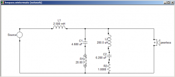
If you have time, it may be interesting to try wintermute's crossover with the LRC network to tame the woofer breakup.
Last edited:
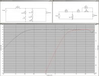
OK well I had a play tonight with the baffle and room sim and the results were not quite what I expected... First I modeled the diffraction using the original FRD consortium Baffle Diffraction Simulator as I have chamfered baffle and MTM format.
I loaded that and the frd file I had in speakerworkshop for my mw144s into holm impulse and divided the mw144s frd by the baffle response file giving the theoretical infinite baffle response (first pic).
I then ran that through the baffle and room diffraction and saved a room response version of the frd. I loaded that back into speakerworkshop and ran the crossover sim using that frd (after matching it for level with the original measurement).
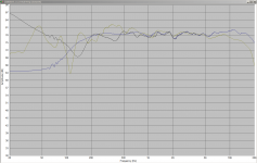
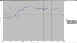
The 2nd pic shows original response (blue) the response using the room corrected frd (black) and the actual in room measured response (green).
Not a good correlation. Though that is somewhat to be expected given that the room is a complex acoustic space. I really should do a measurement (and sim) in a standard room I guess, but that is unlikely to happen anytime soon...
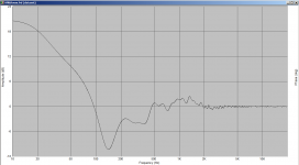
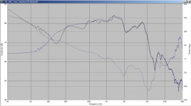
edit: I added the third pic which shows what the output from the baffle and room response was. when added to the baffle corrected response file it is the black curve in the fourth pic.
I loaded that and the frd file I had in speakerworkshop for my mw144s into holm impulse and divided the mw144s frd by the baffle response file giving the theoretical infinite baffle response (first pic).
I then ran that through the baffle and room diffraction and saved a room response version of the frd. I loaded that back into speakerworkshop and ran the crossover sim using that frd (after matching it for level with the original measurement).
The 2nd pic shows original response (blue) the response using the room corrected frd (black) and the actual in room measured response (green).
Not a good correlation. Though that is somewhat to be expected given that the room is a complex acoustic space. I really should do a measurement (and sim) in a standard room I guess, but that is unlikely to happen anytime soon...
edit: I added the third pic which shows what the output from the baffle and room response was. when added to the baffle corrected response file it is the black curve in the fourth pic.
Attachments
Last edited:
I've been having a play in speaker workshop, as I am more comfortable with it for modelling. tweaked a bit more, changed crossover to 2.2K. It looks very flat, I'm worried too flat!
I had a play with Jreave's version as well as it is simpler, but I was a bit worried about what it did to the phase at the notch freq... I haven't put the above back into PCD to see how it compares. Heading for bed.
Tony.
I had a play with Jreave's version as well as it is simpler, but I was a bit worried about what it did to the phase at the notch freq... I haven't put the above back into PCD to see how it compares. Heading for bed.
Tony.
Attachments
I've been having a play in speaker workshop, as I am more comfortable with it for modelling. tweaked a bit more, changed crossover to 2.2K. It looks very flat, I'm worried too flat!
I had a play with Jreave's version as well as it is simpler, but I was a bit worried about what it did to the phase at the notch freq... I haven't put the above back into PCD to see how it compares. Heading for bed.
Tony.
I input the crossover component values to the PCD. I cannot be happier. The results.


This is my next crossover upgrade unless someone convinces me otherwise.
I'm still a bit concerned about the amount of BSC. I was thinking it would be good to do what jReave suggested and make a cut of the woofer response with about 3 - 4.5db of baffle step and run the sims with those. I should try that with my own measurements too (since the boundary sim was not particularly successful).
edit: I always try and get standard values too if it doesn't compromise the performance too much. low pass with standard values below: This actually might even be a little better than above.
Tony.
edit: I always try and get standard values too if it doesn't compromise the performance too much. low pass with standard values below: This actually might even be a little better than above.
Tony.
Attachments
Last edited:
I'm still a bit concerned about the amount of BSC. I was thinking it would be good to do what jReave suggested and make a cut of the woofer response with about 3 - 4.5db of baffle step and run the sims with those. I should try that with my own measurements too (since the boundary sim was not particularly successful).
edit: I always try and get standard values too if it doesn't compromise the performance too much. low pass with standard values below: This actually might even be a little better than above.
Tony.
I already checked rounding off the components to stock values and some to parts I have on hand. They all work fine.
Since I use the bookshelfs at above 100 Hz. The effect of reducing BSC may not be too audiable. I will wait until I finish and test your latest iteration before I make any further decision on the BSC. I hope that jReave may have some suggestion before I order the parts.
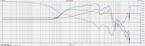
OK I've run the sim with 3db of baffle step applied, and 4.5db of bafflestep applied on my MTM's (as per jReave's method in response modeller). Due to the room modes its a bit hard to gauge, but it looks like perhaps I should only have been doing the crossover based on around 3db of Baffle Step (I used outside measurements which effectively give full baffle step in the FR's used for modeling).
The difference between 3db and 4.5db is not great...
flip side is that "house curves" I've seen tend to slope down, so maybe if eqing for house curve, having a little more BSC won't matter as it will mean less HC eq?
Speaker placement for the in room measurement (it was only one of the two) was approx 20" from rear wall, approx 28" from side wall.
so to explain, the black curve is the theoretical response with NO room effects. Green is rear wall/room adding back in 1.5db, and blue is rear wall/room adding back in 3db.
Tony.
Attachments
Last edited:
I haven't got a lot of time to look at things right now so I'll just make a few comments.
I like Tony's tweeter xo a little better than mine - it's just a little bit smoother. The parallel cap and resistor is a simple but elegant solution. For the woofer, either filter appears to look good.
I notice that there are very slight differences between the 2 xo programs - the FR is running just a little hotter above about 1000Hz in PCD than in Speaker Workshop. I have no idea which is more accurate. I've only used PCD before and liked the results so I would probably tweek Tony's xo just a touch so it is flatter in PCD.
I notice that the power response is lower around the xo, about 1000Hz - 4000Hz, so keeping the on-axis response flat right across the board should balance things out nicely. And as the quality of the drivers is high, I don't think there should be any reason to deviate from a flat FR to start off with.
Before ordering parts, I would also look at the changes necessary when using the 4.5dB baffle loss file. My guess is that reality is going to be a little closer to this than the full baffle step loss only because I notice when looking at other speakers using the same woofer that all of them are pretty much using a smaller coil value than 2.5mH. So note what the differences are in the xo between 6dB and 4.5dB losses and make sure you have the small value differences in caps and resistors around in order to make any changes immediately. When you start out with bigger coils, you can of course unwind them to produce smaller values. Hopefully you might have a multimeter that reads mH which is going to make that a lot easier.
I haven't got a lot of time to look at things right now so I'll just make a few comments.
I like Tony's tweeter xo a little better than mine - it's just a little bit smoother. The parallel cap and resistor is a simple but elegant solution. For the woofer, either filter appears to look good.
I notice that there are very slight differences between the 2 xo programs - the FR is running just a little hotter above about 1000Hz in PCD than in Speaker Workshop. I have no idea which is more accurate. I've only used PCD before and liked the results so I would probably tweek Tony's xo just a touch so it is flatter in PCD.
I notice that the power response is lower around the xo, about 1000Hz - 4000Hz, so keeping the on-axis response flat right across the board should balance things out nicely. And as the quality of the drivers is high, I don't think there should be any reason to deviate from a flat FR to start off with.
Before ordering parts, I would also look at the changes necessary when using the 4.5dB baffle loss file. My guess is that reality is going to be a little closer to this than the full baffle step loss only because I notice when looking at other speakers using the same woofer that all of them are pretty much using a smaller coil value than 2.5mH. So note what the differences are in the xo between 6dB and 4.5dB losses and make sure you have the small value differences in caps and resistors around in order to make any changes immediately. When you start out with bigger coils, you can of course unwind them to produce smaller values. Hopefully you might have a multimeter that reads mH which is going to make that a lot easier.
jReave, thank you for the suggestions. I will use PCD to play with the 4.5dB and 3.0dB BSC file you sent earlier and compare them to the full BSC results. Due to my day time work loads, I may not report back until after the weekend.
- Status
- This old topic is closed. If you want to reopen this topic, contact a moderator using the "Report Post" button.
- Home
- Loudspeakers
- Multi-Way
- The crossover for a modest DIY bookshelf speaker project