The problem is not the crossover method. Baffle step compensation is only correct outside (or if you remove your rear wall for example).
The difference between the two woofer plots represents not lost energy, but energy that is in contention. It can get tied up in room modes before it reaches you.
The first line of defense against the baffle step is the baffle itself.
Then comes careful placement, then using the resulting response to make EQ decisions, then deciding whether the time delays have made EQ impossible or not.
Allen, I am glad that this thread caught your attention.
I am just an hobbyist with limited resources and have to deal with the WPF in speaker placement.
This is my first design attempt of a bookshelf after building a few published designs. First of all, it is for the fun of it. Being an engineer, the feeling of "I did it" is great.
Following the advice of Jeff Bagby (PCD author) and Paul Carmody, I found that a crossover design accounting for the baffle diffraction is more practical than one using the infinite baffle frequency response in my average (12 x 20 feet with 8 ft ceiling) basement room.
I am sharing my experience and looking for other's approach dealing with BSC for further improvement.
I mostly listen to classical and older folk vocal. In speaker design, I like the old British sound. Many commercial bookshelf in today's market use vented design and have an artificial mid bass boost that I found objectionable. It is straightly a matter of personal taste.
6" bass is a horrible speaker IMO. Very hard to get working on a flat baffle.
Michael Chua might inspire though. The SEAS ER18RNX is almost identical to the Nomex 830875:
"STARLING" (Seas 27TDFC + Seas ER18RNX) Bookshelf by AmpsLab
See, separate bafflestep! BW3 and some consideration of the midrange shout problem.
Here's a few sketch ideas in ascending order of desirability. You've doubtless looked at Troels' notch ideas already.
The first one doesn't shout, but it booms at the bottom. LR2
The second one shouts a bit but works well otherwise, it's the old Mark K ER18RNX design at heart. LR2
The third one is a bit Michael Chua'ish and a quite tidy BW3. But big component count.
The fourth BW3 one interests me and works at every level as far as I can see.
Problem is, if you get the slopes right, you run into time alignment problems. Happily BW3 doesn't mind that. FWIW, these were modelled on 20L closed box, except the second design which was a reflex tower IIRC. But it shouldn't matter much. Good luck.
Attachments
Last edited:
keilau, I'm not familiar with .csp files. How do I open those?
It is the configuration file that you load into the Jeff Bagby's Passive Crossover Designer 7 (2007) Excel Spread Sheet. The Macro function must be enabled in the Microsoft Excel program.
I used Jeff's tool for most of my simulation. I am finding time to try XSim too.
Your later post with the screen captures show some interesting componet values, including 0.00 mH L2 and 99999.00 resistor in one of the RLC notch filter. Can you take a look? The menu appears very similar to Jeff Bagby's PCD in style, but the content is very different
Last edited:
Hi keilau, I mentioned earlier about using the target responses, I don't think you understood (based on your projectdayton-mk.csp). Please find attached a modified version.
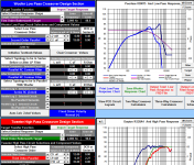
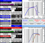
The target response should be set to your desired acoustic slope NOT the target electrical response. See the screen shot. I took your original 2Khz cross point, lowered it slightly to 87db and set it to 4th order LR. Then adjusted components to get a reasonable match to the curves. No attempt to improve phase matching was made, as this is just to demonstrate what others have been saying with respect to varying L1 to get the BS that you want.
Hope that clears things up... I used your min_phase version of the dayton frd.
The first screen shot shows how your targets were set in the csp, not very useful. The second shows when they are set to something meaningful.
Third and fourth shots of the FR and Reverse null.
If you tweak the component values to match the targets then the rest should start to fall into place.
Note I didn't notice the zobel on the woofer, you could try without it as well, or alternatively put in an rlc shunt across the woofer tuned to the freq of the woofers breakup.
edit: couple of minor tweaks resulted in third FR graph (changed zobel to RLC and changed series resistor on tweeter to cap+resistor in parallel in series with tweeter)..... note that the version of csp attached is without these tweaks.
Tony.
Attachments
Last edited:
It is the configuration file that you load into the Jeff Bagby's Passive Crossover Designer 7 (2007) Excel Spread Sheet.
I used Jeff's tool for most of my simulation. I am finding time to try XSim too.
Your later post with the screen captures show some interesting componet values, including 0.00 mH L2 and 99999.00 resistor in one of the RLC notch filter. Can you take a look? The menu appears very similar to Jeff Bagby's PCD in style, but the content is very different
Right. I tend to not actually save my work in PCD that way - I just save the whole Excel spread sheet itself.
Xsim btw uses the same calculations that Jeff designed for PCD - it just has a different user interface and doesn't require Excel.
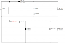
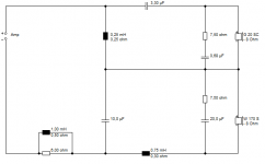
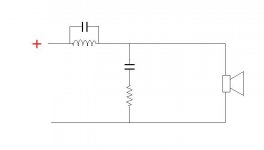
For example, you can add a tanking resistor to the main inductor in xsim quite simply (or so I'm told since I haven't used it) but in PCD, you have to get a little creative. So you set L2 to 0 in the Low Pass section (but still keep the coil's series resistance there) and essentially replace it with a parallel LCR circuit placed in series before the xo. So L2 is now found in the LCR filter (2.2mH). But I really don't want an LCR filter, I just want to add a cap in parallel to the main coil, (so an LC circuit) so I set the R value to something huge which in parallel, turns its value to 0. (sorry, I misspoke in my last post and said I was setting the capacitor to 0)
So it's just a 2nd order electrical on the woofer but the main coil has a small cap in parallel with it and I've added an extra resistor to the parallel leg of the circuit. See attached if words have failed to clear that up.
Set it up the way I have in your version of PCD and watch the way everything works together.
Attachments
Hi keilau, I mentioned earlier about using the target responses, I don't think you understood (based on your projectdayton-mk.csp). Please find attached a modified version.
Tony.
Tony, thank you for taking the time.
The "projectdayton-mk.csp" was my effort 10 months ago and seem to work well with the infinite baffle type FRD in simulation. I found the result not satisfactory in real world listening.
The latest effort "projectdayton-dreydel_baf-comp.csp" followed the advises from Jeff and Paul to include the baffle diffraction effect. The FRD was updated to "peerless830875_minpha.FRD".
I thought the date stamps of the 2 csp files should be clear and did not bother to include any clarification. I am sorry about the confusion.
Your attached zip file seems to be very small in size. I will download and check it out. Thank you again.
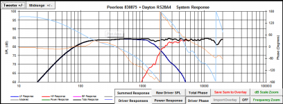
Update with the PCD results using your csp file.

Last edited:
The re-combination of baffle step energy and the direct sound might (typically) produce a nett result somewhere between the two responses. This is why it is broadly recommended to make partial compensation.
The catch is that this response is unlikely to be flat. Also this may amount to a different issue (wrt dealing with it) as it goes above the room frequency.
The catch is that this response is unlikely to be flat. Also this may amount to a different issue (wrt dealing with it) as it goes above the room frequency.
Last edited:
The re-combination of baffle step energy and the direct sound might (typically) produce a nett result somewhere between the two responses. This is why it is broadly recommended to make partial compensation.
The catch is that this response is unlikely to be flat. Also this may amount to a different issue (wrt dealing with it) as it goes above the room frequency.
I honestly flipping give up with bafflestep. As you say, you rarely apply the full 6dB correction. Less always sounds better to me, particularly on dynamics, which is another trade-off. Big bass coils kill the liveliness, IMO.
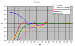
Troels Gravesen had something very interesting to say with his frankly unsatisfactory Nomex 830875 2.5 way project.
Look how positioning and room gain and the Allison cancellation boundary effect plays havoc with the theory, below. The harsh soft-dome tweeter was a struggle too.
Attachments
Last edited:
Nicely put.I honestly flipping give up with bafflestep.
It's enough to make a person want to find a way to eliminate the baffle step and 'room step'.
The usual suspects: parametric EQ, absorption and aligning the wall reflections for a favourable combination, are a mixed bag. The first doesn't help much in the time domain, the second takes a lot of damping material and makes one wonder why not just build a bigger baffle. The third is very touchy to set up and won't guarantee a smooth directivity index.`
They work better or worse depending on the baffle and room transition presented, so naturally work has to be done here first. One other option is holding the baffle step to below the room frequency where the response can be actively augmented (multi-sub style). I've used this up to 800Hz before with very specific modes and it works, although the helping woofer was mono.
Keilau, excuse me going into such detail, my intent was not to overload but to throw some ideas out there. I notice you have concerns about this region, which is responsible for the tactile feel, such as the sound of a vocalist bumping the microphone, breathing and so forth that you can faithfully reproduce but normally only with suitable effort.
Tony, thank you for taking the time.
The "projectdayton-mk.csp" was my effort 10 months ago and seem to work well with the infinite baffle type FRD in simulation. I found the result not satisfactory in real world listening.
The latest effort "projectdayton-dreydel_baf-comp.csp" followed the advises from Jeff and Paul to include the baffle diffraction effect. The FRD was updated to "peerless830875_minpha.FRD".
I thought the date stamps of the 2 csp files should be clear and did not bother to include any clarification. I am sorry about the confusion.
Your attached zip file seems to be very small in size. I will download and check it out. Thank you again.
Update with the PCD results using your csp file.
View attachment 500213
Something very wrong there! Should have been the same as the first fr in my post.... will download the attached zip on my home pc and see what gives..
edit: I just downloaded the zip file I attached unzipped to a different location. Loaded your peerless830875_minpha.FRD and peerless830875-mod.zma files for the woofer. then the RS28A-MLSjb1.frd and RS28A.zma for the tweeter.
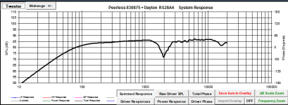
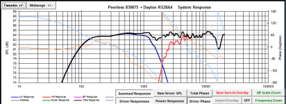
I then loaded the projectdayton-mk_wintermute.csp file. result is as I posted before, so there is nothing wrong with the csp file... OK now I see you were displaying with a 20db range on the plot so it looks much worse than it is. My original posted graph was 70db scale (which is a bit too far the other way. Your first plot is on an 40db scale, if you display it with 20db it won't look so pretty
I also note that you don't have any driver offset in the sim. If you want any chance of getting the phase right in the sim you will need to put in Z offset and vertical offset.
Tony.
Last edited:
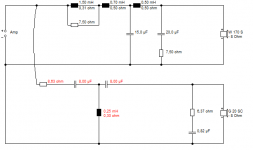
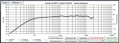
Now this is getting a little extreme, but it is to illustrate a point (ie that you can do baffle step just using a bigger coil).
I've put in vertical offset of 150mm for the tweeter and Z offset of -25mm for the woofer (which are probably reasonable)..
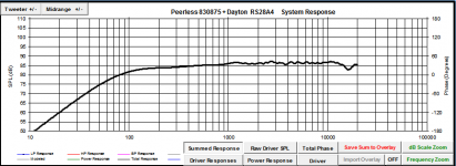
The response is +- 1db from approx 130Hz to 15Khz, you might get better with an optimiser, but that is already extremely flat!
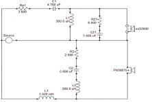
The first one I posted was done quickly, and I was not going for a huge amount of BS compensation. This one isn't necessarily full BSC but it's close. I'm assuming you will be augmenting these with a sub anyway. Again I haven't tried to optimize the phase tracking, but it is not too bad.
So no trickery here, just an rlc in paralell with the woofer to tame (somewhat) the breakup and the R//C on the tweeter to bring up the top end a little.
Tony.
I've put in vertical offset of 150mm for the tweeter and Z offset of -25mm for the woofer (which are probably reasonable)..
The response is +- 1db from approx 130Hz to 15Khz, you might get better with an optimiser, but that is already extremely flat!
The first one I posted was done quickly, and I was not going for a huge amount of BS compensation. This one isn't necessarily full BSC but it's close. I'm assuming you will be augmenting these with a sub anyway. Again I haven't tried to optimize the phase tracking, but it is not too bad.
So no trickery here, just an rlc in paralell with the woofer to tame (somewhat) the breakup and the R//C on the tweeter to bring up the top end a little.
Tony.
Attachments
Keilau, excuse me going into such detail, my intent was not to overload but to throw some ideas out there. I notice you have concerns about this region, which is responsible for the tactile feel, such as the sound of a vocalist bumping the microphone, breathing and so forth that you can faithfully reproduce but normally only with suitable effort.
Allen and Steve (System7), I really appreciate the comments from the two of you who discuss the depth of the issue that I am looking for. I have gone through 3 stages in the past year.
- The first effort a year ago was a total failure with a far too forward result. I traced it to not accounting for the BSC.
- Using L1/C1 adjustment seemed to go the other way with a somewhat recessed midrange and a mid bass bump.
- A separate series LR network in the woofer path seems to work ok to my ears.
What is the most practical crossover topology to effect the partial baffle step compensation that gives me the best chance of the right sound?
Last edited:
Now this is getting a little extreme, but it is to illustrate a point (ie that you can do baffle step just using a bigger coil).
I've put in vertical offset of 150mm for the tweeter and Z offset of -25mm for the woofer (which are probably reasonable)..
The response is +- 1db from approx 130Hz to 15Khz, you might get better with an optimiser, but that is already extremely flat!
Tony.
Tony, many, many thanks. I downloaded the csp and will try it after work today. I like the idea of a RLC network to tame the woofer which should work better than the series RL network I did.
Baffle step is a tricky business, as Allen and Steve have said. What's worse is getting in room measurements (to see what is really going on) is also damn hard!! (If you're considering doing in room measurements check out the mmm thread If you have your speakers out a reasonable distance from the walls (a couple of feet) and not too close to side walls, then close to full BSC may work out ok.. I think with your sealed enclosures you are going to be heading closer to the full BSC end of the spectrum, though as can be seen here --> http://www.diyaudio.com/forums/multi-way/262246-moving-mic-measurement-10.html#post4181220 perhaps not
Tony.
Tony.
Baffle step is indeed tricky. So what I do in terms of simulation is create a few different woofer files with varying amounts of baffle step loss and then work out a xo for each case. Then I let my ear decide which one seems most accurate and enjoyable and adjust accordingly.
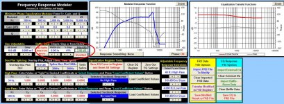
Sound confusing?
It's actually very simple thanks once again to Jeff B. Go back into Response Modeler and import your peerless file with the full 6dB of bsc. Now look at the screen grab below and notice what I've circled in red. This is a function that will adjust the baffle step loss either up or down.
In your case, you want to select "Inverted" and for a small speaker like yours, I would model 2 more cases - one with about 4.5dB of baffle step loss and another with 3dB. For those, select "% Steps" of about 19% and 41% respectively. Save each of those files, then extract minimum phase as usual and then try each one in PCD. For comparison, I've attached my results below (you'll need to change the file extension back to .frd).
I encourage you to go through this process starting with the full 6dB of loss and then moving on to the other 2 cases because, among other things, it will help you again to see how the baffle step is simply handled by the main woofer coil. You should also see that once you find an agreeable xo for the 6dB situation, you can keep the same topology for the other cases but just need to make small changes to a few components.
Btw, an LCR will indeed work on your woofer's 4500Hz peak but a single tanking cap added to the main inductor will do the same job with just 1 component. Again, you've got to play around with it in PCD to see how easily it works.
Attachments
Troels Gravesen had something very interesting to say with
his frankly unsatisfactory Nomex 830875 2.5 way project.
Hi,
There is nothing about it being unsatisfactory at that link.
rgds, sreten.
- Status
- This old topic is closed. If you want to reopen this topic, contact a moderator using the "Report Post" button.
- Home
- Loudspeakers
- Multi-Way
- The crossover for a modest DIY bookshelf speaker project