Hi
Ebay:
RIBBON CABLE FLAT: 3' (fEET) 16 way AWG 28 (7 X 0.127m - eBay (item 370416337887 end time Jan-31-11 01:31:14 PST)
or ask these sellers
Sanyo SF-P101N items - Get great deals on Business Industrial, Electronics items on eBay.com!
JC
Mistakenly burned the cable with my soldering iron. Hope this is the right place to ask this question. Thanks!@
Ebay:
RIBBON CABLE FLAT: 3' (fEET) 16 way AWG 28 (7 X 0.127m - eBay (item 370416337887 end time Jan-31-11 01:31:14 PST)
or ask these sellers
Sanyo SF-P101N items - Get great deals on Business Industrial, Electronics items on eBay.com!
JC
Hey Peter,
I found the JVC unit and will attempt to build the transport, and hope you don't mind some rookie questions. It appears the Blackgates are no longer available. Any recommendations? Also, I'm confused about where one installs the citizen crystal; that's only if adding a clocked output...correct? Thanks.
I found the JVC unit and will attempt to build the transport, and hope you don't mind some rookie questions. It appears the Blackgates are no longer available. Any recommendations? Also, I'm confused about where one installs the citizen crystal; that's only if adding a clocked output...correct? Thanks.
I intend to test a bunch of "available" caps in the next couple of weeks as I want to make a transport for my sister that's good but not too expensive - will post my findings in the original Shigaclone thread (or here if Peter doesn't mind).
I have tried Panasonic FC already and found them far inferior to any of the Black Gates...
I have tried Panasonic FC already and found them far inferior to any of the Black Gates...
When the display board is trimmed like in pics here: http://www.diyaudio.com/forums/audio-sector/160373-cd-transport.html#post2068891 you can use the 4 pads to mount resistor and connect wires there. However, this only works for trimmed display board, otherwise you will damage the chips on main board.
It's best to find out which pads connect to the LED, and solder wire and resistor there, power wire is connected to 10K resistor first. LED is powered from first cap on regulator board (18V or so) , reading after resistor is most likely less than 5V.
It's best to find out which pads connect to the LED, and solder wire and resistor there, power wire is connected to 10K resistor first. LED is powered from first cap on regulator board (18V or so) , reading after resistor is most likely less than 5V.
Hi PD,
Need a little help again if you don't mind,I got a LA6541D it's a dip no SMT's in stock problem is it's layout is different, It seam each set of 6 pins have a + and - spindle motor ,a spindle sense and a pin to a microprocessor,I have traced most of these out, but I don't have the pinouts for the sled or the spindles,would you have a more detailed set of drawings that show chip function? I 've got the motors running and the sled moves and have zeros in the read out so I am close but not there yet,As always if you don't mind helping me out I appreciate it!
Thanks 10-6
Attachments
Unfortunately besides data sheet and manual for the boombox I don't have anything else available, you can always try to Google for more info.
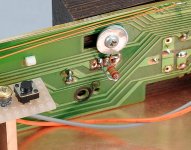
In picture below, I connect red+ to resistor lead on left and black- to pad on right. You can follow the traces to see how they connect to LED
Yes. I've trimmed the board and mounted identically to your photo. Just to make sure: from the rear-view of mounted board, I should connect red+ to left pad and the black- to the pad on right of resistor....right? Thanks.
In picture below, I connect red+ to resistor lead on left and black- to pad on right. You can follow the traces to see how they connect to LED
Attachments
Last edited:
Ulf, uniformity of backlight depends heavily on the surface of the glass wedge behind LCD, and the white reflective sheet behind that glass. Lapping one or both sides of the wedge to a "cloudy" finish and/or replacing the sheet with some kind of matte paper should even out the backlight (but possibly also make it a bit dull).
While you have the display in pieces, you could use the opportunity to change the diode to a different colour - or replace it with a small bulb like I did, for that classic warm glow")
While you have the display in pieces, you could use the opportunity to change the diode to a different colour - or replace it with a small bulb like I did, for that classic warm glow
Last edited:
Success
Been listening to my shigaclone for a couple of days and am thrilled with the sound. Will never hook up my old player again, which is rated in the mags as a well-regarded budget audiophile "giant killer". I used Silmics for PS and for C916. I splurged on the S102 and MK132 digital out. The only glitches are that forward skip and the remote are inoperable, but I've been too busy listening to start troubleshooting those. Many thanks again to PD.
I jumped online to buy another JVC unit, but it looks like they are now truly unavailable. Any chance of discovering another drive unit and developing shigaclone version 2?
- Status
- This old topic is closed. If you want to reopen this topic, contact a moderator using the "Report Post" button.
- Home
- More Vendors...
- Audio Sector
- The CD Transport