Saturnus, I just stumbled across this thread incidentally, and I have to say - I think Andrew is right.
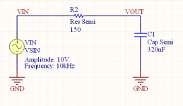
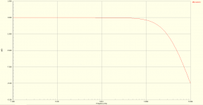
I've gone and simulated the resistor/piezo network to show you. Attached are the circuit and a graph of the frequency response of the network, with C1 being the piezo driver, VOUT being the voltage across the piezo driver and VIN being the input voltage waveform. The response looks like a characteristic RC lowpass filter to me.
Below is the SPICE code for the simulation, so you can verify:
Code:
*Schematic Netlist:
C1 0 VOUT 320nF CAP
R2 VOUT VIN 150 RES
VIN VIN 0 DC 0 SIN(0 10V 10kHz 0 0 0) AC 1 0

.SAVE 0 VIN VOUT VIN#branch @VIN[z] @C1[i] @R2[i] @C1[p] @R2[p] @VIN[p]

*PLOT AC -1 1 A=@C1[i]

*Selected Circuit Analyses:
.AC DEC 100 1 1E4

*Models and Subcircuits:
.MODEL CAP C()

.MODEL RES R()

.END
Attachments
Saturnus, I just stumbled across this thread incidentally, and I have to say - I think Andrew is right.
I've gone and simulated the resistor/piezo network to show you. Attached are the circuit and a graph of the frequency response of the network, with C1 being the piezo driver, VOUT being the voltage across the piezo driver and VIN being the input voltage waveform. The response looks like a characteristic RC lowpass filter to me.
Change the position of the cap and the resistor.
Yes, then it becomes a high pass filter.
What does this have to do with your application, though? The piezo is driven by the voltage across it, no? And the piezo is represented by a capacitor in this instance. So, we should be comparing VOUT (the voltage across the piezo/capacitor) to VIN, as I've done.
What does this have to do with your application, though? The piezo is driven by the voltage across it, no? And the piezo is represented by a capacitor in this instance. So, we should be comparing VOUT (the voltage across the piezo/capacitor) to VIN, as I've done.
Change the position of the cap and the resistor.
Ohm and Kirchoff, long before the relatively worthless CTS app note, said that it wont make any difference. A series circuit will always have the same response no matter what the sequence. If there are no polar parts within it then you can even flip them. If you do that with the tweeter here, of course it will be 180 out of phase in one direction, but the frequency response will be the same.
I figured he didn't mean that we should directly measure the voltage across R to directly measure the voltage across C. That would be fundamentally confusing. It might be important to mention that that no matter what you measure, the tweeter is only going to play the voltage across C.
It might also be helpful to actually run an impedance sweep on the tweeter. Manually would be good enough, just pick a dozen frequencies and plot them out. This test wont lie to you.
I think Martin Colloms has written about piezo speakers and didn't seem to harber any odd faith in them. You could check his books.
Last edited:
Awesome looking ghettoblaster there!Sorry for late feedback. But here it goes:
I left the HP-100:s running with pink noise for at least 40h before heading of to Roskilde. My conclusion is that they definitely changed character to the better, sounding more "natural". However, I still think that they are to "soft" and lacking that last "hi-end" treble (that might be impossible to achieve with piezos though...).
Field test report:
I'm really happy with the performance of the Boominator @ this years Roskilde festival! It sounded great and was fairly easy to carry around late nights. Thanks to the aluminum edges and the round metal corners it also became virtually indestructible.
I also added a uC-controlled giant LED VU-meter (using audio as input) on the backside which attracted even more people to the dance parties at the camp
YouTube - Boombox with built in VU-meter
Battery life was excellent. I used two 7.2Ah SLA:s (not at the same time though) and charged them during the day with a 20W solarpanel from solarlab.se.
I have been also looking for some kind of VU-meter or Spectrum-meter, but haven't found anything that would fit. Where did you buy your VU-meter?
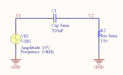
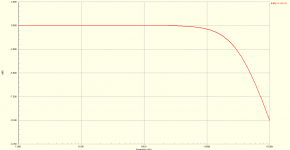
OK. I've swapped the position of the capacitor and resistor. I've also renamed the voltages to a more generic V1 and V2. Now, the output waveform is going to appear across the capacitor (representing the piezo), which is (V1 - V2). The input waveform is V1. I've attached a plot of the frequency response. Still a low pass filter.
Below is the SPICE netlist:
Below is the SPICE netlist:
Code:
*Schematic Netlist:
C1 V2 V1 320nF CAP
R2 V2 0 150 RES
VIN V1 0 DC 0 SIN(0 10V 10kHz 0 0 0) AC 1 0

.SAVE 0 V1 V2 VIN#branch @VIN[z] @C1[i] @R2[i] @C1[p] @R2[p] @VIN[p]

*PLOT AC -1 1 A=@C1[i]

*Selected Circuit Analyses:
.AC DEC 100 1 1E4

*Models and Subcircuits:
.MODEL CAP C()

.MODEL RES R()

.END
Attachments
An externally hosted image should be here but it was not working when we last tested it.
here's my beast y'all .. not quite the same design as the boominator (didnt read of it untill after i made mine) but works a charm
")
Hey guys
I've been browsing this and other forums for a while and little more than a month ago i decided to build my own boombox.. The boominator was an excellent inspiration and i've built something quite similar..
I shot some pictures while making it.. Enjoy
Cutting the wood.. I used 12mm birch plywood, as in the Boominator.
The weather was really nice, so i made myself an ad-hoc workstation outside
The amp6basic built into an aluminum cabinet.
Workstation moved inside the carport
Cutting holes and starting the assembly of the box:
Making sure the woofers fit before making final assembly of the sides
Assembling the center compartment
Putting together the electronics for testing etc..
Polishing after first round of polyfilla
Making sure the lid fits etc
Just finished third round of polyfilla and a lot of polishing
Cutting out holes for vents
Making some final tests and adjustments before paint etc etc..
First layer of primer done
Carving out the lid
After second round of primer and first layer of paint:
After second layer of paint and putting together the parts:
Its pretty big.. I made it 20cm longer than the boominator as i wanted more space in the center compartment for future addons
Nearly finished with added speaker grills:
It sounds AWESOME.. I've already used it for several outdoor events and people are astounded by the looks and sound of it.. People come up to me asking where they can buy something like that - I love the look on their faces when i tell them i built it myself
I still have several additions planned but due to lack of funds atm im waiting until spring to add more stuff too it..
I'm very happy with my results and even though the weather is getting colder i've used it a lot!
Thanks a lot for all the great info on this thread, its been amazing
I've been browsing this and other forums for a while and little more than a month ago i decided to build my own boombox.. The boominator was an excellent inspiration and i've built something quite similar..
I shot some pictures while making it.. Enjoy
Cutting the wood.. I used 12mm birch plywood, as in the Boominator.
An externally hosted image should be here but it was not working when we last tested it.
An externally hosted image should be here but it was not working when we last tested it.
The weather was really nice, so i made myself an ad-hoc workstation outside
An externally hosted image should be here but it was not working when we last tested it.
The amp6basic built into an aluminum cabinet.
An externally hosted image should be here but it was not working when we last tested it.
Workstation moved inside the carport
An externally hosted image should be here but it was not working when we last tested it.
Cutting holes and starting the assembly of the box:
An externally hosted image should be here but it was not working when we last tested it.
An externally hosted image should be here but it was not working when we last tested it.
Making sure the woofers fit before making final assembly of the sides
An externally hosted image should be here but it was not working when we last tested it.
An externally hosted image should be here but it was not working when we last tested it.
Assembling the center compartment
An externally hosted image should be here but it was not working when we last tested it.
Putting together the electronics for testing etc..
An externally hosted image should be here but it was not working when we last tested it.
An externally hosted image should be here but it was not working when we last tested it.
Polishing after first round of polyfilla
An externally hosted image should be here but it was not working when we last tested it.
An externally hosted image should be here but it was not working when we last tested it.
An externally hosted image should be here but it was not working when we last tested it.
Making sure the lid fits etc
An externally hosted image should be here but it was not working when we last tested it.
Just finished third round of polyfilla and a lot of polishing
An externally hosted image should be here but it was not working when we last tested it.
An externally hosted image should be here but it was not working when we last tested it.
Cutting out holes for vents
An externally hosted image should be here but it was not working when we last tested it.
Making some final tests and adjustments before paint etc etc..
An externally hosted image should be here but it was not working when we last tested it.
First layer of primer done
An externally hosted image should be here but it was not working when we last tested it.
Carving out the lid
An externally hosted image should be here but it was not working when we last tested it.
After second round of primer and first layer of paint:
An externally hosted image should be here but it was not working when we last tested it.
An externally hosted image should be here but it was not working when we last tested it.
After second layer of paint and putting together the parts:
An externally hosted image should be here but it was not working when we last tested it.
An externally hosted image should be here but it was not working when we last tested it.
An externally hosted image should be here but it was not working when we last tested it.
Its pretty big.. I made it 20cm longer than the boominator as i wanted more space in the center compartment for future addons
An externally hosted image should be here but it was not working when we last tested it.
Nearly finished with added speaker grills:
An externally hosted image should be here but it was not working when we last tested it.
An externally hosted image should be here but it was not working when we last tested it.
An externally hosted image should be here but it was not working when we last tested it.
An externally hosted image should be here but it was not working when we last tested it.
It sounds AWESOME.. I've already used it for several outdoor events and people are astounded by the looks and sound of it.. People come up to me asking where they can buy something like that - I love the look on their faces when i tell them i built it myself
I still have several additions planned but due to lack of funds atm im waiting until spring to add more stuff too it..
I'm very happy with my results and even though the weather is getting colder i've used it a lot!
Thanks a lot for all the great info on this thread, its been amazing
Phaedras, thats awesome, well done on the build.
how long did it take and what drivers are you using?
Thanks, im pretty happy about it
I used 4 Piezo tweeters
And 4 x p.audio HP-10w as used in the Boominator..
I think i spent about 40 hours on research reading here, and other forums.. And I spent about a week making it with 2-7 hours work each day.. So in total it was around 70-80 hours
Love it Phaedras, it looks great! What do you think about the tweeters, can they match the hp10w's output ok?
I've been thinking about building a mono boominator, with 2 drivers, mounted magnet to magnet, which should be around half the size.
Would this work ok? I guess it wouldn't put out as much volume but it would be a lot smaller. I could easily build a 2nd one and bolt them together making it (sort of) modular.
Also, I noticed some people in this thread have used driver with a neo magnet, would these also gain efficiency by mounting them magnet to magnet in the same way that the hp-10w's gain efficiency?
Love it Phaedras, it looks great! What do you think about the tweeters, can they match the hp10w's output ok?
I've been thinking about building a mono boominator, with 2 drivers, mounted magnet to magnet, which should be around half the size. (...)
Thanks man.. Im really happy with it..
I started out with 150ohm series resistors on the tweeters and then tried out 120 and 100 aswell and the sound wasnt that great.. The tweeters couldnt really match the hp-10w's and it sounded a bit hollow..
But when i removed the resistors and just hooked up the tweeters with full signal it sounded great, so thats the config im sticking with now.. It might be because the spl of the tweeters is 95 and the woofers is 96.. I dont know - someone more knowledgeable might be able to clarify this
Hello everyone, and thanks for a very interesting thread!
I began reading it pre-Roskilde '10, after I finished my Partybox. But after watching and listening to some Boominators and some Boominator-inspired boomboxes at Roskilde festival I knew that my boombox, allthough great looking, wasn't loud enough.
I've just started manufacturing a Boominator myself, and i promise you, pictures will follow.
The design is almost entirely based on Saturnus original, but i decided to go bigger, and tuned it a little different. I bought 4 x P.audio HP-12W. The tweeter is the same as Phaedras.
Me and my brother started manufacturing it on sunday.
Here are some pictures of the old one, and what-soon-is-to-be-the-new-one.
http://sphotos.ak.fbcdn.net/hphotos..._465064347958_570882958_6642826_8357510_n.jpg
I began reading it pre-Roskilde '10, after I finished my Partybox. But after watching and listening to some Boominators and some Boominator-inspired boomboxes at Roskilde festival I knew that my boombox, allthough great looking, wasn't loud enough.
I've just started manufacturing a Boominator myself, and i promise you, pictures will follow.
The design is almost entirely based on Saturnus original, but i decided to go bigger, and tuned it a little different. I bought 4 x P.audio HP-12W. The tweeter is the same as Phaedras.
Me and my brother started manufacturing it on sunday.
Here are some pictures of the old one, and what-soon-is-to-be-the-new-one.
An externally hosted image should be here but it was not working when we last tested it.
An externally hosted image should be here but it was not working when we last tested it.
An externally hosted image should be here but it was not working when we last tested it.
http://sphotos.ak.fbcdn.net/hphotos..._465064347958_570882958_6642826_8357510_n.jpg
An externally hosted image should be here but it was not working when we last tested it.
An externally hosted image should be here but it was not working when we last tested it.
My brother welding a circular jig for the mill cutter.
An externally hosted image should be here but it was not working when we last tested it.
Picking up the AMP6-BASIC from 41hz Audio today!
I bought the assembled version due to the lack of my soldering skills. Previously, I've only managed to solder speaker terminals, and larger stuff.
But curios as I am, I also ordered a practice solder kit... It feels a little better to have messed up something för 2 € , than something for 50 €
Pictures soon to come!
I've seen that some of you people installed the amplifier in an small aluminium box. I've been searching for this type of box, but so far I have not find any close to Sweden... Anyone who can offer a link?
(...)
I've seen that some of you people installed the amplifier in an small aluminium box. I've been searching for this type of box, but so far I have not find any close to Sweden... Anyone who can offer a link?
Hey Closure
Thats gonna be one big boombox with the 12" drivers
I bought my aluminum enclosure here, but im not sure they ship out of the country.. But there are LOTS of distributors around.. Im pretty sure you can go to any electronics shop/website and buy it.. Its very comon
Hope you find what you need and the build is coming along!
- Home
- Amplifiers
- Class D
- The Boominator - another stab at the ultimate party machine