To "prove" a point, in my own tests with piezos and LM3886's I noticed that the best overall sound was to be had with only 1 ohm in series with the tweeter (active crossover of course)... just enough to keep the amplifier stable. Even 2 or 3 ohms seemed to allow the element to do too much of it's own thing, even if frequency response wasn't actually changing. If you get 150 ohms on there you may as well throw ideas of fidelity right out the window.
Naw, it's a low pass.
Nope. Spice it! Measure it! Really don't care but it's a high pass.
If you get 150 ohms on there you may as well throw ideas of fidelity right out the window.
You have to use the correct and calculated resistor value. Just throwing in 150 Ohms is like saying that it doesn't matter what impedance a tweeter has but just throw in a 2 uF capacitor regardless.
I understand that these simple techniques (One resistor.) are often thrown at piezo elements to keep everything on the mega cheap cheap, to the point that how to get the best out of anything piezo is hardly well known, but this chronic abuse of these sometimes fairly hi-fi capable devices is a major part of their poor reputation.
No no no, the series resistor is in most cases and for most piezo the best option for correct filtering.
What gives the piezos a bad reputation is people not having the faintest clue about what really goes on and just throw in a random (most often much too low) resistor value.
A series resistor on a piezo is a simple high-pass filter. Fact of life, live with it.
It has to be the correct calculated value though in order to filter away the lowest part of it's frequency range. Allowing a piezo to play those makes it sound "piezo"-like.
The best frequency to place the x-over point is in the middle of the lowest peak. That never fails to give astonishing results.
Well, I'd never put 150 ohms on any piezo element, I only mentioned that because someone else said that's what they were using.
Just in case you're still thinking I'm having some sort of problem with theory, 150 ohms into .15uF will give you a turnover point of 7077Hz. Piezo's are voltage driven devices. They don't care about current. That's the source's problem.
Just in case you're still thinking I'm having some sort of problem with theory, 150 ohms into .15uF will give you a turnover point of 7077Hz. Piezo's are voltage driven devices. They don't care about current. That's the source's problem.
Just in case you're still thinking I'm having some sort of problem with theory, 150 ohms into .15uF will give you a turnover point of 7077Hz. Piezo's are voltage driven devices. They don't care about current. That's the source's problem.
Exactly. My HP100s are 320 nF so that roughly the wanted 3.5KHz roll-off needed. Actually it starts the roll-off in the low peak which is a 4dB peak, and since it's a butterworth filter it's 3 dB down at the x-over point it just flattens that peak. Making the real acoustic x-over about 2.8 KHz.
Last edited:
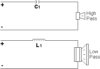
Spice it? Are you serious? Here, which one of these circuits are we talking about:
Guitar Pedals: R-C Filter Calculator
Guitar Pedals: R-C Filter Calculator
Please excuse, Saturnus, but you will not be making a crossover with just a series resistor on a piezo, unless you are looking for a falling with increasing frequency, 6dB slope.
Every measurement I've ever made tells me differently. So please excuse me but I trust my own measurement and ears more than any random person on the internet.
Ask anyone who has ever tried doing it my way, and they'll tell you the same thing.
Spice it? Are you serious? Here, which one of these circuits are we talking about:
Guitar Pedals: R-C Filter Calculator
I see your problem ... you think it's a R-C filter. It's not.
It's a butterworth filter. The capacitor is the load, the resistor is the variable
")
A filter made of one R and C is always an RC filter. There are no fancy tailored responses to be had. Go back to that site and look at where "OUT" appears on the left drawing, the low-pass one. You may as well consider this the situation on your piezos, because the voltage at "OUT" is what appears on your element.
Saturnus, you're missing me just because you don't think I have anything to say. Not good.
Take your crossover schematic if you will. You can call the resistor the "variable" if you want, but what Always happens to the voltage across the capacitor with rising frequency, with any value or R?
I repeat, the piezo element is a voltage driven (responding) transducer.
Take your crossover schematic if you will. You can call the resistor the "variable" if you want, but what Always happens to the voltage across the capacitor with rising frequency, with any value or R?
I repeat, the piezo element is a voltage driven (responding) transducer.
If you have nothing relevant to add. Please stay out of this thread. The multitude of people (I know of at 37 currently) that has actually built this system knows that I'm right.
If what you said was correct there would be no high frequency output at all, and certainly not the in the 13Khz range where my Boominator measure (relatively) flat to. So all I can say is that you try it yourself and be amazed.
If what you said was correct there would be no high frequency output at all, and certainly not the in the 13Khz range where my Boominator measure (relatively) flat to. So all I can say is that you try it yourself and be amazed.
Maybe there is some odd reason why you don't think your source has any output above 13k? Maybe?
No, it's because I must have set the encoder to that by mistake at some point I discovered after Krilli's post. I did some digging and it's my mp3 encoded from mid 2002 to early 2005 (co-incides with a computer change) that had that wrong setting. That was when I was designing it but I didn't use mp3s for measurements. I used WAV files which doesn't have the bandwidth limitation
Here is some help from Planet 10. My opinion varies somewhat from that expressed here, but the on the fundamentals, no. (except for the little slip at the beginning about using parasitic Xc to roll off the bottom). The reason people get fooled into thinking that works is the driver simply has no response below resonance anyway.
planet_10 hifi
The advantage of using the capacitor to level match a piezo is that it has a flat frequency response with the parasitic capacitance of the element. But this still doesn't on its own handle the problem of most piezos getting quite resonant and wild when driven from high impedance. The only way to handle that is to do crossover and level matching before the tweeter power amp, and only using as much series resistance as required to keep the amp from chirping or oscillating, but even though the power efficiency of the piezo driver is preserved here, the addition of extra amp channels loses it all again. The only resulting improvement is sound. However, because of the quite high voltage/power efficiency of piezo tweeter, a very low power linear amplifier (say, a good buffer on a good opamp), running only the frequency band of the tweeter, can be used effectively in battery applications. This can result in top grade fidelity.
Last edited:
Carseneau,
The sure amps are just fine. However, the 2x100w requires a 24v power supply to get anything close to that wattage. The 2x25 (2020) amp just has a bit more power than the 2024 (2x15w), and most people around here seem to think the chip sounds better as well.
--Buckapound
The sure amps are just fine. However, the 2x100w requires a 24v power supply to get anything close to that wattage. The 2x25 (2020) amp just has a bit more power than the 2024 (2x15w), and most people around here seem to think the chip sounds better as well.
--Buckapound
Buckapound,
I just ended up ordering both amps anyways (DTA-2 and the Sure 2x25W) incase I screw one up or something. They are so cheap I'm not too worried.
Now all I need to do is find a way to charge my iPod. Would I just be able to get a USB car charger and wire it up with the battery and still use the stereo at the same time? I assume so, but is there anything I should worry about?
Would a solar panel with specs like this be helpful for my 18AH SLA or is it just a waste of time?
Solar Panel Rated at 1.8W (125mAmps@14.4V)
I really need to be able to make this thing last for at least 3 days, hopefully 18 or so hours a day. If the solar won't help enough for that long I may just have to get a bigger battery.
Also, is it a good idea to put a fuse between the power and the amp just incase (if so what size fuse?)
Thanks again for all this helpful information, I'm really getting excited about this stereo!
-Craig
- Home
- Amplifiers
- Class D
- The Boominator - another stab at the ultimate party machine