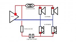
Here's a sketch of the commonly used passive x-over for the PHT 407N.
What does the dsp in the cAmp control?
[URL=http://s478.photobucket.com/user/Shortrope/media/Boomfilter.jpg.html] [/URL]
What does the dsp in the cAmp control?
[URL=http://s478.photobucket.com/user/Shortrope/media/Boomfilter.jpg.html]
 [/URL]
I was wondering, how did you guys ensure perfect 90 degrees angles while gluing and drilling? I posed this question at my local hardware store but amazingly they didn't have any idea in this situation (since the plywood is relatively thin).
Or this is a case of: perfect doesn't exist and in this case aligning it by eye is good enough?
The tried and true way for case assembly is to glue it up, lightly clamp, measure diagonals to ensure it is square, adjust as needed, firmly clamp the assembly and confirm it is still square.
With the boominator that results in a very complicated glue up. I prefer to glue the outside ends to the bottom of the Boominator. Then the center dividers, then the middle divider. Go slow. If it takes 6 separate glue ups, that is fine.
See if you can find a rafter framing square like this:
Rafter Squares | MSCDirect.com
You can check to see if it really is square by laying it against a straight edge and drawing a vertical (90* to straight edge) now flip the square over and to the same thing. The lines should be parallel. If they are not, then find another square.
Those squares have a nice edge that can be clamped to the work surface. That can make things easier too. One other thing to watch is that the vertical speaker brace (where magnets are glued) is correctly positioned. If it is off center you will have a lot of problems gluing on the baffles.
Hope this helps. If you want I can take a few photos tonight. Just let me know.
Last edited:
The cAMP that's about to go to market doesn't have a DSP.What does the dsp in the cAmp control?
The model with a DSP (currently still a prototype) uses the DSP to control the DC/DC converter dynamically, providing a slight audio delay so the DSP can keep up.
Eventual plan is for the DSP to do missing fundamental bass enhancement ala Waves MaxxBass. It's amazing what kind of sound you can get out of small portable Bluetooth speakers using that tech, and I'm imagining a Boominator equipped with something like that, with its efficient speaker design and a 24V capable amp would be absolute madness.
The card design is largely complete, however the DSP stuff needs some good research hours put into it.
The 'Smart Amp' IC's (like the TAS5766M) seem like a very cool amp IC for something like a Boominator. They keep an eye on mechanical and thermal factors via entered speaker models and measurements, then it dynamically switches between real and psycho bass extension. They have several other 'smart functions' to push speakers to the max without going over limits. Everything intergrated in a simple IC that only costs a couple of bucks. However you need some software for programming, don't think the price will be too steep if spread over several boards. I might attempt a PCB design with it for use in the upcoming MINI (how's that going Saturnus?). Way less complicated than all the stuff Gmarsh is doing  Powered of a 5S li-ion or 6S LiFe it'll kick aaassss.
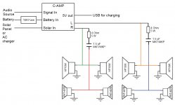
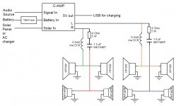
This is my updated diagram. I added the filter components for the PHT407s (thanks Saturnus for posting the filter values). I also added a fuse on the battery input. Just to confirm, the cAMP takes care of the filtering for the HP10s, correct?
Anything missing here?
Anything missing here?
Attachments
No, the cAMP is a full range stereo. If it filtered away the high end there'd be no signal for the tweeters. You need the series inductor.
Oh, right, that makes sense. Sorry for the basic questions, I just want to make sure I have everything right before I get started building.
By the way, I received my HP10Ws and PHT407Ns today from Loudspeakersplus. Everything was packaged up perfectly and they arrived so quickly. I'll be shopping for my crossover components and looking for the 12mm filmed birch plywood while I wait for the cAMP to become available.
Attachments
The 'Smart Amp' IC's (like the TAS5766M) seem like a very cool amp IC for something like a Boominator.
Yes, they look icredibly cool.
I wonder when the first modules will occur.
Last time i looked the boominator thread up, motorola piezos were still recommended.
The new tweeters must be a big step forward.
Are there any boominators built around Cologne, Germany?
I would like to listen to one once.
The tried and true way for case assembly is to glue it up, lightly clamp, measure diagonals to ensure it is square, adjust as needed, firmly clamp the assembly and confirm it is still square.
With the boominator that results in a very complicated glue up. I prefer to glue the outside ends to the bottom of the Boominator. Then the center dividers, then the middle divider. Go slow. If it takes 6 separate glue ups, that is fine.
See if you can find a rafter framing square like this:
Rafter Squares | MSCDirect.com
You can check to see if it really is square by laying it against a straight edge and drawing a vertical (90* to straight edge) now flip the square over and to the same thing. The lines should be parallel. If they are not, then find another square.
Those squares have a nice edge that can be clamped to the work surface. That can make things easier too. One other thing to watch is that the vertical speaker brace (where magnets are glued) is correctly positioned. If it is off center you will have a lot of problems gluing on the baffles.
Hope this helps. If you want I can take a few photos tonight. Just let me know.
Thanks for the response
I was already thinking of going very slow, gluing two plates at a time, using a flat surface as reference point. It still won't really be ideal I guess. Pictures are always welcome of course!
Strange, I thought I posted this yesterday but apparently I didn't press submit..
No, the cAMP is a full range stereo. If it filtered away the high end there'd be no signal for the tweeters. You need the series inductor.
I actually miss the point, why there is a series inductor needed for HP10W, it just acts as a low pass? (Nothing to do with the tweeters)

The TAS5768M is a really interesting looking chip - it's basically a TPA3116/8, SigmaDSP style audio processing core and DAC all in a single chip, which almost seems perfectly suited to a Boominator amp.The 'Smart Amp' IC's (like the TAS5766M) seem like a very cool amp IC for something like a Boominator. They keep an eye on mechanical and thermal factors via entered speaker models and measurements, then it dynamically switches between real and psycho bass extension. They have several other 'smart functions' to push speakers to the max without going over limits. Everything intergrated in a simple IC that only costs a couple of bucks. However you need some software for programming, don't think the price will be too steep if spread over several boards. I might attempt a PCB design with it for use in the upcoming MINI (how's that going Saturnus?). Way less complicated than all the stuff Gmarsh is doingPowered of a 5S li-ion or 6S LiFe it'll kick aaassss.
I looked into it, but TI wants me to spend over a grand on a set of development boards in order to actually develop for the part, and until I do that, I can't get any 'proper' information on the chip. The datasheet gives a "load your instructions and coefficients to this address" memory map, but no further information on the DSP. And there's things I don't even know about the chip - eg, is the DSP able to toggle a couple of the GPIO pins in order to program the DC/DC converter output voltage? What's it got for delay memory? etc. I don't even know if the chip will do everything I want. If they open up this stuff I'll give the chip a second look, but for now I'm sticking with the ADAU1701/TPA combo.
Now the TPA3251D2 would make for an interesting Boominator amp...
Quiescent current. It's hard to beat a TPA3116/3118 in 1SPW mode.What about double TPA3132D2 filterless?It's much cheaper.
I actually miss the point, why there is a series inductor needed for HP10W, it just acts as a low pass? (Nothing to do with the tweeters)

He means that if the cAMP itself filtered out the high frequencies, like I had incorrectly mentioned/diagrammed earlier, there would be no signal for the tweeters.
Since it outputs the whole spectrum, you need the full crossover circuitry.
Yesterday I tried a test-drive with my halfinator cabinet half-finished, as I was working on the electronics compartment. I wired all drivers and crossover components (407N tweeters). I connected my TPA3116D2 amp 50WX2 Official Version Finished TPA3116D2 Class T Digital Power Amplifier Board | eBay with the mono-mod as described in section 7.4 in this document http://www.ti.com/lit/ds/symlink/tpa3116d2.pdf
I also increased the gain as described in section 7.3 by replacing the 20K resistor with a 39K
finally I replaced the big and small 1uF caps on the Rin side, with these 0.1uF caps 15 x 0 1uF 100V 5 Mylar Film Capacitors | eBay
I connected my bluetooth module Bluetooth 4 0 Audio Receiver Board Wireless Stereo Sound Module for Car Phone PC | eBay
and made the output of the bluetooth module mono by connecting both L and R to an individual 10K resistor (so 1 resistor for each) and then pairing the output of that to the input of the modded amp.
I connected both the module and the amp to my LiFePO4 6S2P (less than 20V) and connected my phone..
it sounded horrible!
there was this weird nagging sound, which to me sounds like interference or something (although I have no knowledge on this subject whatsoever). There was also the hiss of the tweeters which I understand is due to the high output level (I did not add a potmeter yet), but the volume level did not even seem that loud to me.
I then connected the speaker straight to my home-amp and that sounded crisp and clear, so luckily nothing went wrong there.
So it goes wrong somewhere further down the line. I added a separate battery for the bluetooth module (9V) but that didn't help. I added a potmeter to check the different volume levels. As expected the stationary hiss of the tweeters went away as I turned the potmeter to the left. But the weird 'interference' sound stayed when I would play music.
I suspect I messed something up with the amp while modding it, but I cannot see it.
Next I will try taking the bluetooth module out of the equation and input directly to the amp to eliminate causes further.
Any input/ideas are very much appreciated!
Quiescent current. It's hard to beat a TPA3116/3118 in 1SPW mode.
I got it down to 32mA at 12V in PBTL 32dB, and 24mA at 12V in BTL 26dB configuration. What did you got?
I connected my bluetooth module Bluetooth 4 0 Audio Receiver Board Wireless Stereo Sound Module for Car Phone PC | eBay
and made the output of the bluetooth module mono by connecting both L and R to an individual 10K resistor (so 1 resistor for each) and then pairing the output of that to the input of the modded amp.
I connected both the module and the amp to my LiFePO4 6S2P (less than 20V) and connected my phone..
it sounded horrible!
there was this weird nagging sound...
Those bluetooth modules are sometimes nasty. I had success in different configurations using an LC-Filter at the BT-module power line. You want to use a High-Z-Ferrite and a huge Low-ESR-Cap. (Something like 1000R@100MHz for the ferrite and 2200uF Low-ESR cap) You should also use only 1 ground connection from the BT-module to the amp-board. Use low-gain, like 20-26dB for the amp.
If this all is not working, you should go for a BT-module with differential output, using an amp with differential inputs.
Last edited:
I got it down to 32mA at 12V in PBTL 32dB, and 24mA at 12V in BTL 26dB configuration. What did you got?
It's between 10mA and 14mA in 1SPW mode at 12V and 24V respectively. Ternary modulation mode is just staggeringly efficient.
Thats way less than the datasheet states? (with no load and no filter)
Datasheet: 12V 20-35mA, 24V 32-50mA
So how?
The data sheet only list the range for BD modulation mode.
It's pretty much explained in the data sheet. Firstly, in 1SPW mode the outputs idle at 15% of the modulation frequency. Secondly, ternary modulation is much more efficient due to only going true differential or full bridge at -6dB. Up to that point it runs in a virtual single ended output mode having 1 hot output, which can be either actual output, and the other nulling to a virtual ground state.
There are some addition requirements to 1SPW or ternary mode though. You must use fully differential LC output filters. And these must be matched to a reasonable degree. +-5% component tolerance maximum. No saturation of output inductors is allowed and neither is voltage sagging in capacitors. You cannot use the PLIMIT pin to make a virtual lower voltage rail for the outputs in 1SPW mode.
Last edited:
- Home
- Amplifiers
- Class D
- The Boominator - another stab at the ultimate party machine


