Yes, it really is that simple. Two amps might be enough, but sometimes with bigger capacitors on the power supply especially, you might get a rush of current that might blow the fuse, but you can always go to a higher-rated fuse if that's the case.
Go ahead and hook everything up and see how you like the sound. These kind of projects are real simple from an electronics point of view--it's not like designing some new kind of amplifier. Let the amp burn-in for a few days and see if the speakers are OK. You can get a pair of the cheap piezo tweeters and add them to see if you like the sound better.
Just messing around until you get things sounding better to your ears, that's the fun of these projects.
--Buckapound
Gaichuke said:Yet another question...
This time regarding the bipolar design in boominator. It's true that you get almost 360 degree of music blasting, but you can only be on one side of the thing itself.
So doesn't this design "waste" half of the power because you can only music mostly from two speakers at a time?
Or does the increased sensitivity of bipolar design cancel this?
I'm now contemplating on bipolar design, but I'm afraid that I'm loosing half of the power to the people behind the boombox.
What do you think?
Can someone answer this please?
Construction will start tomorrow and I'm still undecided of what I'll do.
I'm not a big expert on bipolar speakers but I do have a pair of dipoles in my living room.
A lot of that sound coming from from the back speakers is not wasted. It rolls around the box t5o the front and also bounces off any flat surfaces behind it and that bounced sound tends to create a much wider field of sound than you otherwise get from a pair of speakers close together. If you are worried about it, it should be easy enough to put in a switch that will let you turn off the back pair(s) of speakers when you want to. You could actually use a three-position switch and change the polarity as suits the situation.
--Buckapound
This would be in outdoors, so I doubt there is that many flat surfaces for sound to bounce off.
Based on that I guess it's not a total loss at least.
Second one is automatic bass compensation; try placing a normal speaker outside on a grass field and play something, now as you walk around it you will find that on the opposite side of where the speakers are facing treble and midrange will be lower than directly in front of it, this is because the air works as a gentle acuostic filter of higher frequencies but letting lower frequncies pass. Now in a bipolar design you add the response of the front facing driver with acoustically filter back facing drivers and thereby get a completely free bass boost.
Based on that I guess it's not a total loss at least.
Marine speaker suitability?
Hi,
Given that my system will be used primarily on a boat, I was checking out Marine speakers as being an option.
I found the following specifications for some 6" and 6x9", high-sensitivty Dual marine speakers which sound like they would be OK, though clearly not in the same size range as the P Audio HP-10W woofers.
http://www.dualav.com/support/manuals/dms.pdf
Looking at the DMS655SM, the DMS692 and DMS 652.
Can anyone comment on their likely suitability for such a project?
Benefits would be:
-durability to elements
-smaller size/weight/enclosure required
Costs would be:
-Decrease in bass/sound/volume
Oh, and thanks buckapound for the previous reply.
Any info appreciated
-Vincent
If i use the batteries in parallel and buy a 12V to 24V DC/DC converter, will it work properly or do the converters have a very bad efficiency?whelibob said:ZOTA, nice looking ghettoblaster. Which speakers have you chosen?
Anyone here done a ghettoblaster with 24V? im planning on going for it with sure-electronics 2x100W amplifier, but i noticed a problem. While using two 12V batteries in series, the voltage of the other battery always drops faster then the other ones. Any way gettin around it?
Cheers
Let see ...
I chose 150 Ohm resistors from listening tests. I originally used 133 Ohm resistors but the piezos overlapped the woofers too much. Please note, that I have explained earlier in this thread how piezos work and how to calculate the resistor value if you use other piezo than those I use.
Yes, the magnets really touch eachother, they're actually glued together. As I already explained this design is entirely based on that because the structural strength with a centerbrace and the speakers themselves is so much rigid than a traditional design that you can use much thinner, and thereby light materials.
I chose 82 Hz because calculations showed 80 Hz was optimal, so a tiny overtuning is ok plus it makes up for cabinet might be a bit less closed than expected from for example from a slightly bad glueing or the cable holes not being completely siliconed.
Maybe I should try to start a new thread with all the questions (many of which a the same) answered.
Welcome back Saturnus,
I hope you enjoyed Roskilde this year as well.
About my questions... damn, I guess I'm still too ignorant with this stuff.
I mean, I've read this thread through several times already and I recapped the ones where you talk about the piezos, and I still don't get it. I've now reach the conclusion that the resistor choice for the piezos depend on the capacitive property of the piezo element itself, but I have no idea how to calculate it.
I think I got the 0.22 mH coil choice now though, if I use this formula,
4ohm = 2*pi * F * 0.00022H
F = 2900Hz
So the crossover point for the drivers is roughly 3000 Hz, right?
edit: found this from an another thread. Too bad that the manufacturer doesn't tell me the capacitance of my piezos.
I hope you enjoyed Roskilde this year as well.
About my questions... damn, I guess I'm still too ignorant with this stuff.
I mean, I've read this thread through several times already and I recapped the ones where you talk about the piezos, and I still don't get it. I've now reach the conclusion that the resistor choice for the piezos depend on the capacitive property of the piezo element itself, but I have no idea how to calculate it.
I think I got the 0.22 mH coil choice now though, if I use this formula,
4ohm = 2*pi * F * 0.00022H
F = 2900Hz
So the crossover point for the drivers is roughly 3000 Hz, right?
Most piezo horns have a sharp peak in the 2KHz range and then a deep dip in the 3-4KHz range before becoming more linear above about 5KHz. Generally it's that initial range peak that account for most of the bad qualities in a piezo horn, so generally they should just be used over 5KHz. Luckily that's an easy fix. Just add a series resistor. That will work a highpass filter in itself and at the same time make the piezo a reasonable load for the amp since a piezo is a capacative load the equation is exactly the same as for a normal 1st order highpass but instead of calculating the capacitor, you calculate the resistor value you need. R = 0.159 /(C*f) R = resistor value in Ohms C = piezo's capacitance in Farads f = desired x-over frequency in Hertz(a good starting point is 3.5KHz).
edit: found this from an another thread. Too bad that the manufacturer doesn't tell me the capacitance of my piezos.
I don't use a coil on woofers in the piezo version, and yes, you diagram is technically correct but I parallel the drivers directly on the amps outputs because that way you don't have to change anything if you go with an amp9basic which has 4 outputs instead.
Here's the diagram posted in post 285
http://www.diyaudio.com/forums/showthread.php?postid=1742547#post1742547
And yup, I enjoyed Roskilde immensely again this year
Here's the diagram posted in post 285
http://www.diyaudio.com/forums/showthread.php?postid=1742547#post1742547
And yup, I enjoyed Roskilde immensely again this year
Glad to hear it, maybe I'll take a stab at Roskilde too next year, never been there yet.
But really, no coils after all? The first post that mentions the 0.22 mH must be from a previous version then?
I thought this was the way to install the speakers if using Amp6Basic, 2x8 ohms in parallel per channel to get to 4 ohm per channel. Or did you mean that you just plug everything straight to the output instead of "combining" wires like in my drawing?
I'm starting to feel quite stupid again...
Ok,
my speakers have arrived, it's time to do some installing.
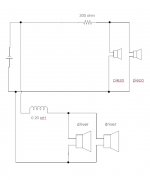
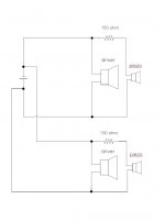
My setup is very similar to boominator, 4xdrivers combined with 4xpiezos. Drivers are 8 ohm, so they will be put in parallel combination together with piezos as described in the picture in my previous post, but without any coils after all.
I have one question though, in my picture I've put 300 ohm resistor for the piezos. But from yet another re-reading of this thread, I believe that what I should do is exactly the opposite, to use 75 ohm resistor instead. I used 300 ohms because I thought that was the way to go when I wanted to have 150 ohm resistance per piezo tweeter.
Sooooo... which way is the correct way when using the setup in my picture?
Thank you for the answers.
my speakers have arrived, it's time to do some installing.
My setup is very similar to boominator, 4xdrivers combined with 4xpiezos. Drivers are 8 ohm, so they will be put in parallel combination together with piezos as described in the picture in my previous post, but without any coils after all.
I have one question though, in my picture I've put 300 ohm resistor for the piezos. But from yet another re-reading of this thread, I believe that what I should do is exactly the opposite, to use 75 ohm resistor instead. I used 300 ohms because I thought that was the way to go when I wanted to have 150 ohm resistance per piezo tweeter.
Sooooo... which way is the correct way when using the setup in my picture?
Thank you for the answers.
Wiring up 4x 4-ohm speakers for Boombox
Hi,
Hopefully getting around to making the first version of my boombox this weekend.
I got given 4 x 40watt 4ohm 6.5" Clarion marine speakers.
The sensitivity is only 89db, but should be OK for round one until I plan ahead and get something a little bigger and more sensitive.
I got the thiele-small parameters from Clarion and according to WinISD I need a 23.5l enclosure for each pair of speakers.
I have two 12v, 7ah batteries that I will wire in parallel and a solar panel on it's way to help with the charging/battery life.
I am running a Lepai LP2020 Class T amp, rated for 4ohms.
I was wondering if someone could help with the best way of wiring the speakers for my 4ohm amp. If I wire them in series each cpair will be at 8ohms, if I wire them in parallel each will be 2ohms.
-Should I then wire a resistor in series/parallel with each pair of speakers to get closer to 4ohms?
-Or should I be fine either at 8ohms/2ohms?
-Or should I only use 2 speakers total as the gains from the extra speakers will be negligible?
Any help appreciated...
-Vinnie
Wow, 50 liters! That's gonna be a gigantic boombox. Can that be right, folks?
Anyway, there's no point in hooking up resistors to raise the resistance, because then you're just wasting power. I suggest hooking them up to the amp with no cabinets and try it as just one pair, then try with both sets in series (8 ohms), and see what you like better. It obviously won't sound like it will when they're in the cabinets, but you should be able to gauge the relative loudness.
And of course, if you're using this thing in situations where people will be listening from all sides, then that's one more reason to use both pairs.
One additional solution would be to add a second amp to power the second pair of speakers (you can add this later). You can have a switch which will allow you to turn them off when you don't need them or want to conserve battery life.
FYI, with my 6 watt solar panel, I can run a 2020 at mid-volume in full sunlight. It helps to have the solar panel separate so it can be positioned for best solar exposure, rather than stuck to the top of the box.
--Buckapound
Hi Buckapound.
Thanks for reply.
I was thinking 23.5 litres per speaker pair was a lot, but that was what I was getting from WinISD (it also recommended 11.8litres for a single speaker which fits with a doubling of capcaity for 2).
If you (or anyone else) know more about this I would appreciate a double-check.
I was given the following parameters by Clarion (these were all they provided):
-Peak Power = 80W
-Continuous Power = 40W
-fs = 82Hz
-Vas = 8.4l
-Qts = 0.54
-Qms = 1.12
-Qes = 1.04
-Re = 3.2 ohm
-SPL = 89db
-Bl = 4.43
I realised resistors would drain power, but I thought that it was important to match the impedance of amps/speakers. As long as I am not going to strain the amp too much I will go with pairs of speakers in series for now. And I like the idea of getting another amp and running a set of speakers off each...those Lepai's are only €25 delivered or something.
Was it you that was using the Brunton Solaris 6, I think I read about it somewhere on here? Are you happy with it?
I have been eyeing them on Amazon etc, and may just have to pick one up the next time I am in the US for work, currently about $100. I love the idea of it being foldable and easily moveable.
Cheers,
-Vinnie
Sorry, my skills are more in metalwork and assembly that with math and calculating so somebody else will have to help with the box sizes.
Yes, that was me with the Brunton. Works great, folds up flat, weighs next to nothing. I just bring it when I need it and plug it in.
--Buckapound
Yes, that was me with the Brunton. Works great, folds up flat, weighs next to nothing. I just bring it when I need it and plug it in.
--Buckapound
- Home
- Amplifiers
- Class D
- The Boominator - another stab at the ultimate party machine