And that incredible strength is all with screws and glue when putting together the different sides?
No extra support needed like the blue on the picture:
No extra support needed like the blue on the picture:
An externally hosted image should be here but it was not working when we last tested it.
Hmmm..
I just think a halfboominator will be too hard to carry around.. it's should be made so i can take it with me in a bus. and will be used for outdoor use after school on fridays and on the beach ect. in the summer days .. hmm maybe i can make the halfboominator easier to carry if it had some wheels") hehe, i'll think about that..
hehe, i'll think about that..
thanks for the comparison.. sounds nice!
I just think a halfboominator will be too hard to carry around.. it's should be made so i can take it with me in a bus. and will be used for outdoor use after school on fridays and on the beach ect. in the summer days .. hmm maybe i can make the halfboominator easier to carry if it had some wheels
hehe, i'll think about that..thanks for the comparison.. sounds nice!
And that incredible strength is all with screws and glue when putting together the different sides?
No extra support needed like the blue on the picture:
No. Just follow the drawing.
No. Just follow the drawing.
Well fair enough. Just have to convince the woodwork teacher about the strength then.
Well fair enough. Just have to convince the woodwork teacher about the strength then.
The strength lies in the engineering. Try looking at the drawing and then remember that the drivers themselves connect to both the sides and centerbracing. Then you realize that the box cannot flex in any direction and therefore don't the added strength from lists.
another Q to the Q list..
When you buy a amp6basic assambled. how assampled is it? like, how much DIY is there to do.. Does it come with a powersuply? is it easy to put it in a box and make a panal for it.. i have a soldering iron ect.. It's about the only concern i has, because im not the big DIY audio man.
When you buy a amp6basic assambled. how assampled is it? like, how much DIY is there to do.. Does it come with a powersuply? is it easy to put it in a box and make a panal for it.. i have a soldering iron ect.. It's about the only concern i has, because im not the big DIY audio man.
I've been reading and reading and searching both here and at 41hz forum and I don't understand how you connect a rocker switch to the Awake/sleep pins on amp6 basic.
This is the rocker switch I have, https://www.elfaelectronics.com/elfa3~ex_en/elfa/init.do?item=35-031-02&toc=0
Is it supposed to be connected like in the picture?
Ofc I have tried to see if it works but it doesn't.
I haven't soldered the wires, but I quess it should work before I do that?
Can someone please upload a picture of how you connected it and describe it for me?
This is the rocker switch I have, https://www.elfaelectronics.com/elfa3~ex_en/elfa/init.do?item=35-031-02&toc=0
Is it supposed to be connected like in the picture?
Ofc I have tried to see if it works but it doesn't.
I haven't soldered the wires, but I quess it should work before I do that?
An externally hosted image should be here but it was not working when we last tested it.
Can someone please upload a picture of how you connected it and describe it for me?
I think it's easier to just quote the assembly instructions.
You cannot use the AWAKE pin to turn on the amp on and off without also switching the UNMUTE pin too. And that will give instabilities in the DC output, so don't do that. Just use a switch on the UNMUTE pin instead.
It consumes only 5.5mA (0.066W@12V) in MUTED state. Compare this to that a 7Ah SLA battery self-disharges at a rate of 11.7mA, or twice as much without being used so it actually uses zero power from the battery that wouldn't self-discharge by itself anyways. (Any current draw up to the 12mA is basically "free").
It is NOT recommended to place/remove jumpers when the amp is powered: use a switch (or two). Switching Mute and Sleep/Awake is not useful; just leave on Awake and switch Mute.
You cannot use the AWAKE pin to turn on the amp on and off without also switching the UNMUTE pin too. And that will give instabilities in the DC output, so don't do that. Just use a switch on the UNMUTE pin instead.
It consumes only 5.5mA (0.066W@12V) in MUTED state. Compare this to that a 7Ah SLA battery self-disharges at a rate of 11.7mA, or twice as much without being used so it actually uses zero power from the battery that wouldn't self-discharge by itself anyways. (Any current draw up to the 12mA is basically "free").
Last edited:
I think it's easier to just quote the assembly instructions.
You cannot use the AWAKE pin to turn on the amp on and off without also switching the UNMUTE pin too. And that will give instabilities in the DC output, so don't do that. Just use a switch on the UNMUTE pin instead.
It consumes only 5.5mA (0.066W@12V) in MUTED state. Compare this to that a 7Ah SLA battery self-disharges at a rate of 11.7mA, or twice as much without being used.
Ok thank you!
I just have one more simple question with an simple answer.
The wires can be soldered to the unmute pin, and + is to the left side?
Isn't it just easier to make a switch in between the power supply input and the battery? If you turn it off you will have have no consumption at all (besides the selfdischarge itself).
Up to the self-discharge level any power used is free anyways, and you avoid turn on pops. But yeah, just switching the power on and off is much eaiser.
The wires can be soldered to the unmute pin, and + is to the left side?
Does it matter?
(It was a rhetorical question. It doesn't matter.)
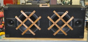
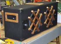
Well, I've not visited this thread much in the past two years but had started on a couple boominators back in 2009, finishing one of them at that time for a Christmas present. It's really cool that you started this thread Saturnus; there are lots of interested members out there! A couple weeks ago I thought it was about time I finished the 2nd one for myself.
I used Goldwood GW-1058 woofers as recommended substitutes for the originals Saturnus used, and am using some cheap copies of the 1165A (I think that's the number) Motorola piezo tweeters. I'm using 20 ohm resistors in series with each tweeter, then 8ohm resistors in parallel with the tweeter & 20 ohm. 8 ohm L-pads are used with this network; a 6.8uF cap is in series with the L-pad input to set the cut off at about 2900Hz.
I've been playing with both the 15w x 2 Sure amp board and their 100W X 2, running either one or two 9VA 12v batts respectively.
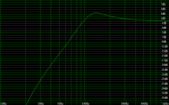
I'm no audiophile but am impressed thus far in the performance, cheap piezos and all. Using WinISD, tuning the enclosure for 70Hz, the response is predicted to be as attached. I'd like to check my work and measure the resonant frequency of box but am not sure how to go about that. I did try monitoring the voltage drop across a 10 ohm resistor in series with the speakers (with an o-scope having amplitude and frequency readout), looking for the point of least current flow. Doing this I found minimum current around 128Hz.....way off from the 70Hz I was aiming for. Is this method flawed? Maybe that technique is only valid for testing a speakers resonance in free air?
I used Goldwood GW-1058 woofers as recommended substitutes for the originals Saturnus used, and am using some cheap copies of the 1165A (I think that's the number) Motorola piezo tweeters. I'm using 20 ohm resistors in series with each tweeter, then 8ohm resistors in parallel with the tweeter & 20 ohm. 8 ohm L-pads are used with this network; a 6.8uF cap is in series with the L-pad input to set the cut off at about 2900Hz.
I've been playing with both the 15w x 2 Sure amp board and their 100W X 2, running either one or two 9VA 12v batts respectively.
I'm no audiophile but am impressed thus far in the performance, cheap piezos and all. Using WinISD, tuning the enclosure for 70Hz, the response is predicted to be as attached. I'd like to check my work and measure the resonant frequency of box but am not sure how to go about that. I did try monitoring the voltage drop across a 10 ohm resistor in series with the speakers (with an o-scope having amplitude and frequency readout), looking for the point of least current flow. Doing this I found minimum current around 128Hz.....way off from the 70Hz I was aiming for. Is this method flawed? Maybe that technique is only valid for testing a speakers resonance in free air?
Attachments
Last edited:
Somehow I wound up with a double post..oops! I"ll add that I mounted the woofers from the outside and am not taking advantage of the efficiency gain from butting the magnets together; I have about an inch between them. Do you think I'd gain a sound benefit by filling that 1" gap with something solid, like a hardwood, gluing the magnets to it to add more structure to the enclosure? The dimensions are not that much bigger than the speaker itself so I thought perhaps this wasn't necessary. I used 1/2" 9-ply birch plywood.
Last edited:
another Q to the Q list..
When you buy a amp6basic assambled. how assampled is it? like, how much DIY is there to do.. Does it come with a powersuply? is it easy to put it in a box and make a panal for it.. i have a soldering iron ect.. It's about the only concern i has, because im not the big DIY audio man.
When you buy a amp6basic assambled. how assampled is it? like, how much DIY is there to do.. Does it come with a powersuply? is it easy to put it in a box and make a panal for it.. i have a soldering iron ect.. It's about the only concern i has, because im not the big DIY audio man.
another Q to the Q list..
When you buy a amp6basic assambled. how assampled is it? like, how much DIY is there to do.. Does it come with a powersuply? is it easy to put it in a box and make a panal for it.. i have a soldering iron ect.. It's about the only concern i has, because im not the big DIY audio man.
It's pretty far along! It's just a question of hooking up wires. No, the power supply is not included, but you can use almost any supply. A simple 12V 1A brick is enough for a well-functioning amp. Higher amperage is better, lower amperage is ... well ... lower amperage is OK in that the amp turns on and plays music! So it's hard to go wrong.
Then you just have to solder the right wires in the right place: Power, switch, input, output. It's easy. It's only a few minutes of soldering, less than an hour of actual work. Couple of hours of planning if you want to be super careful.
In comparison: BY FAR the most complicated part is drilling the panel. And anyone can do that
Isn't it just easier to make a switch in between the power supply input and the battery? If you turn it off you will have have no consumption at all (besides the selfdischarge itself).
Well, actually I never thought about it but it makes sense.
This is how I connect my battery to the amp.
An externally hosted image should be here but it was not working when we last tested it.
Just to be 100% sure, the switch should be mounted before the red marking? (don't know the english word)
When the time comes to connect a solar panel it's just to connect it to the wires, with a regulator between them or am I wrong?
where did you get that battery bastanken
? - i can't seem to find them in that size in europe anywhere...You'll need a proper LiFePO4 charge controller, which is designed to run from a solar panel. Charging a LiFePO4 battery without a controller will overcharge it, damaging the battery and possibly even causing a fire, and a "non-solar" charger might not work.Well, actually I never thought about it but it makes sense.
This is how I connect my battery to the amp.
An externally hosted image should be here but it was not working when we last tested it.
Just to be 100% sure, the switch should be mounted before the red marking? (don't know the english word)
When the time comes to connect a solar panel it's just to connect it to the wires, with a regulator between them or am I wrong?
Something along these lines, I hope there's something a bit cheaper out there somewhere:
MPPT Solar Charge Controller for 12.8V LiFePO4 battery pack
Honestly, I'd go with SLA batteries. They're cheap, they're not *that* heavy, and they're fairly tolerant of overcharging - provided your solar panel isn't too big, you can pretty much just connect it to the SLA and not worry.
- Home
- Amplifiers
- Class D
- The Boominator - another stab at the ultimate party machine