Why it look so terrible? I need an opamp for a headphone amplifier, so i need only 1V peak.
2*pi*25khz*1V=0.157 V/µS. And assuming I need 15V peak then the needed slew rate ist 2.3V/µS.
Why using opamps with much higher slewrate for Audioamplifiers? Or is the 25kHz not enough in my calculating? The human ear hear only up to 20kHz.
2*pi*25khz*1V=0.157 V/µS. And assuming I need 15V peak then the needed slew rate ist 2.3V/µS.
Why using opamps with much higher slewrate for Audioamplifiers? Or is the 25kHz not enough in my calculating? The human ear hear only up to 20kHz.
Last edited:
increasing distortion occurs before you hit the hard slew rate limit depending on input stage details
Distortion In Power Amplifiers shows the bjt diff pair issues as the collector currents become unbalanced to create the i driving the compensation cap to the slew rate limit
degeneration, jfets, multi-tanh or other input diff stage linearization change the relations - as does changing from dominant pole Miller compensation to others such as 2nd order compensation
not all headphones are adequately driven with only 1 Vpeak - 300 or 600 Ohm headphones need more - as do inefficient Ortho Dynamic headphones
Last edited:
increasing distortion occurs before you hit the hard slew rate limit depending on input stage details
Distortion In Power Amplifiers shows the bjt diff pair issues as the collector currents become unbalanced to create the i driving the compensation cap to the slew rate limit
degeneration, jfets, multi-tanh or other input diff stage linearization change the relations - as does changing from dominant pole Miller compensation to others such as 2nd order compensation
not all headphones are adequately driven with only 1 Vpeak - 300 or 600 Ohm headphones need more - as do inefficient Ortho Dynamic headphones
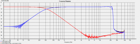
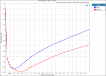
As JCX points out, input stage distortion starts well below slew rate limit, and is a function of input differential voltage. Here is a plot I took this afternoon of an OPA227, in a gain of one, 100kOhm load, +/-18V supplies, 250kHz measurement bandwidth. I measured the THD+N for increasing output amplitude at 20kHz (red) and at 30kHz (blue).
At 30kHz, the slew-rate limited amplitude would be 8.626Vrms (12.2Vpk). But notice that there is no sudden change in the THD+N at this point. The THD+N just continues its rising trend that began even at modest output voltage levels (1.25Vrms). At 20kHz, the slew rate limited amplitude should be 12.94Vrms (18.3Vpk) which is outside the test range. However, again, there is a rising trend of distortion with amplitude.
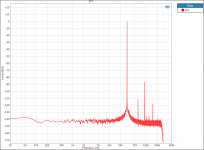
Looking at the FFT for a 5Vrms 30kHz fundamental shows the telltale 3rd and 5th harmonics indicating input stage distortion. The input stage transfer function is a hyperbolic tangent, which only has odd harmonics (The 2nd harmonic is large signal distortion from the output stage).
The transconductance of a differential pair drops significantly as the differential voltage increases. This can be linearized with degeneration resistors but in op amps designed for DC precision these are avoided as they increase offset and noise. Other techniques can be used to flatten the gm vs. differential voltage curve, such as slew-boosting. In a slew-boosted architecture the op amp increases the differential pair tail current in accordance with input differential voltage. But I don't think this technique was around at the time when the OPA227 was introduced.
Attachments
If you need gain use the OPA228, it is specified as 10V/us
For a buffer, no gain, use the OPA227.
That is why Burr Brown gave us the uncompensated and the compensated. Different duties.
Reproducing a 2.4Vac maximum output of a CDP, the OPA227 20kHz plot is showing distortion still down at the minimum of better than -105dB
Johnc,
have you got similar plots for the OPA228?
Last edited:
increasing distortion occurs before you hit the hard slew rate limit depending on input stage details
Distortion In Power Amplifiers shows the bjt diff pair issues as the collector currents become unbalanced to create the i driving the compensation cap to the slew rate limit
degeneration, jfets, multi-tanh or other input diff stage linearization change the relations - as does changing from dominant pole Miller compensation to others such as 2nd order compensation
not all headphones are adequately driven with only 1 Vpeak - 300 or 600 Ohm headphones need more - as do inefficient Ortho Dynamic headphones
I hope you understand why I don't feel comfortable contributing to these threads, I trust your impartial input almost without question.
I find flogging your brand in general somewhat tasteless.
I am happy with the clear statement of Industry affiliation, see no problem as long as we get objective commentary, don't see any "pushing the brand"
this particular thread was intended to be naïve subjectivist's trading "flavors" commentary, has outlived the original poster's welcome here
but as the thread has recently has wandered into engineering of op amps lets not do anything to quash the flow objective info
this particular thread was intended to be naïve subjectivist's trading "flavors" commentary, has outlived the original poster's welcome here
but as the thread has recently has wandered into engineering of op amps lets not do anything to quash the flow objective info
Just to clarify my position here: I was a member of diyaudio long before I took my current role at TI. I did not join this forum with the purpose of promoting a brand or particular product.
I only comment on these threads when I feel I can contribute knowledge or measurements relevant to the topic. My affiliation is clearly stated so that all know exactly where this information is coming from.
I only comment on these threads when I feel I can contribute knowledge or measurements relevant to the topic. My affiliation is clearly stated so that all know exactly where this information is coming from.
Just to clarify my position here: I was a member of diyaudio long before I took my current role at TI.
I did not join this forum with the purpose of promoting a brand or particular product.
I, for one, am very grateful for your generous contributions here. We are all very fortunate that you are willing
to spend some of your scarce time to help those on this forum.
And wich slew rate would fit if I need 1,5V Peak for Audio band(20kHz). If I calculate with the slewrate formula i get 0.18 V/µS.increasing distortion occurs before you hit the hard slew rate limit depending on input stage details
..
If you need gain use the OPA228, it is specified as 10V/us
For a buffer, no gain, use the OPA227.
That is why Burr Brown gave us the uncompensated and the compensated. Different duties.
Are they both similar only the slew rate differ?
@johnc124 Which product from TI ist your personal advice for a opamp for headphone/preamplifier use?
Hi Guys,
I am looking for a pair of single op-amps for the differential to single conversion stage in my DAC. The NJM2114D handles the I/V stage [no intention to change these], while the LME49710 [would like to change these] does the D/S stage.
I find the sound too bright currently and would love to smooth the top end and warmen the sound a bit, giving more body to the bass, but with as little loss in overall detail/resolution as possible. I am using HiFiMAN HE-560 headphones [reference], with a Audio-gd SA31SE amp [slightly warm].
Promising options so far - ADA4627-1, OPA827, OPA1611, LT1028, AD845, ADA4898-1, OPA1641, OPA2604AP, AD8065ARZ, LM6171, AD825ARZ.
Other recommendations welcome.
Any advice would be appreciated!
Thanks
conq
what headphone? - Ohms and sensitivity
portable or desktop?
capable of driving your cans to clean 120 dB peaks instantaneous peaks from exceptional Classical, Jazz recordings?
Sensitivity 119db/mW, 36ohm impedance, portable. Iwant to know how to search the right opamp from all these opamps. I thought a slewrate of 2 and higher is enough for all amplifiers.
The NJM2114D handles the I/V stage [no intention to change these], while the LME49710 [would like to change these] does the D/S stage.
The NJM2114 is a well specified device but that doesn't mean you should assume its blameless or the most suited for your application.
Whatever devices you try, you must back those changes up by checking that no instability has been introduced.
The OPA2604 is the one device in all those that just might offer what you want.
Sensitivity 119db/mW, 36ohm impedance, portable. Iwant to know how to search the right opamp from all these opamps. I thought a slewrate of 2 and higher is enough for all amplifiers.
Can someone "show" that the slew rate for of the opa227 is to worse for an audio amplifier? Because my calculating says its more than enough.
And Douglas Self says:
From Self_Douglas/Small_Signal_Audio_Design.pdf
To produce a full-amplitude 20 kHz sine wave you only need 2.1 V/ms..
2.1 v/ms is plenty providing you give it fair warning a signal is coming ")
If you want to use the OPA227 then you should arrange for a low pass input filter to ensure that the opamp can never see anything that might trouble it... and thats good practice no matter what device you use. Nothing coming off CD (and thats audio... I don't mean hf hash and noise) is going to trouble the 227.
Its up to you to decide if it makes the grade sonically. Its like wanting to do 70mph on the motorway. Do you want a Formula 1 that would exceed the requirement several times over, or will a car with a top speed of 100 be sufficient ? And once the thrill of having the ultimate spec has worn off, which might you actually prefer day to day ?
what do you expect to improve? - high sensitivity and low Z are what DAP/MP3 players are already designed to drive - already have purpose designed op amps for the V and load
most common commodity op amps or even classics recommended for audio are not going to be better for 36 Ohm load
many op amps previously discussed here were designed for ~+/-10 V output, current limit at few 10s mA, have order of 50 Ohm output stage Z - loading them with 36 Ohms seriously distorts their operating conditions from their intended order of kOhm loading
as I keep pointing out with high sensitivity headphones, when you need < 200 mVrms, may often be best interfaced to most amp circuits with audio frequency step down transformers when your lowest V source is 1 Vrms (today's LiIon battery powered portable players)
200 mVrms drives 119 dB/mW 36 Ohm headphones to 120 dB SPL - most listening should be at 1/100 the V = 2 mVrms! - circuit noise becomes a quality problem - transformers are the best way to deal with the gain structure/sensitivity mismatch
Last edited:
BJT drawing input current vs JFET inputs with no current, source impedance being ridiculously low, BJT are ridiculously quieter vs when impedance starts getting high, start getting equal or JFET will be quieter. Current noise adding/part of voltage input why see a lot BJT with stupid big Cap input taking eons to charge up, that low impedance keeps current noise in check. Really can be quite startling just how much quieter you can get some to be vs others etc. These NE5532s are triping me out, Getting closer to what I like with it, real quiet/clear/extended etc still typical BJT sound though, need mess around try something else. Not sure what the hell it is if its just Harmonics/Fundamentals/character but like one minute I Perceive as kinda fake/weird BJT sound the next its like the Detail/lushness is there, more so gets very interesting when get into some major clipping/distortions haha, Like I said it trips me out, trying to think or believe/Perceive what you think you are hearing haha
Last edited:
- Home
- Amplifiers
- Chip Amps
- The best sounding audio integrated opamps