I've revised the board as per marce's suggestions;
Ray
- added a cap at the NE555 Vin
- rerouted tracks to NE555 ground pin
- amended J1 layout so it can use a removable jumper instead of a soldered wire link
An externally hosted image should be here but it was not working when we last tested it.
Ray

Please Add Gnnett: single-ended x1, balanced x1
Hazard500: flip-flop x1
Supra: single-ended x1
Stijn001: flip-flop x1
dwjames: single-ended x1
ichiban: single-ended x1, flip-flopx1
PJotr25: flip-flop x1
Pegasus21: flip-flop x1
skrstic: flip-flop x1
Snicklefritzz: balanced x 1
flowerpot: flip-flop x 2
Umarcus: balanced x 2
Giulio: flip-flop x 1
Caad: balanced x 2
randytsuch:balanced x 1
deanoUK balanced x 1 SE x 1
Vdi_nenna: single-ended X 2
merlin el mago: single-ended x 2
Nikola Krivorov: single ended Х1
pgour : Flip_Flop x 1 + SE x 1
ligascon: balanced x 1 SE x 1
matejS: single-ended x 1
analog_sa: balanced x 1 SE x 1
lukaluka: flip-flop x 1
xaled: flip-flop x 1, single-ended x 1
Anjump123: Single-ended X 2
asanden: balanced x 1 + SE x 1
whmok: single-ended x 2
JimS: balanced X1, single-ended X2
Guglielmope: balanced X1, single-ended X2
iestynrw: balanced x1
torb: balanced x2
Dimdim: balanced x 1
Leon77 : Balanced x 2, Single-Ended x 2
jborden: Balanced x 2
ravid: single-ended x 2
kumori: Balanced x 2
RushBattle: Balanced x 1
francolargo: flip-flop x 1
Barryblue7: Balanced x 1, Single-Ended x 1[/QUOTE]
*Updated my SE and Flipflop counts.
Haven't seen this thread in a while and it's a nice surprise that this is moving along nicely. The balanced and flipflop boards are the same right?
Hazard500: flip-flop x1
Supra: single-ended x1
Stijn001: flip-flop x1
dwjames: single-ended x1
ichiban: single-ended x1, flip-flopx1
PJotr25: flip-flop x1
Pegasus21: flip-flop x2 + SE x2
skrstic: flip-flop x1
Snicklefritzz: balanced x 1
flowerpot: flip-flop x 2
Umarcus: balanced x 2
Giulio: flip-flop x 1
Caad: balanced x 2
randytsuch:balanced x 1
deanoUK balanced x 1 SE x 1
Vdi_nenna: single-ended X 2
merlin el mago: single-ended x 2
Nikola Krivorov: single ended Х1
pgour : Flip_Flop x 1 + SE x 1
ligascon: balanced x 1 SE x 1
matejS: single-ended x 1
analog_sa: balanced x 1 SE x 1
lukaluka: flip-flop x 1
xaled: flip-flop x 1, single-ended x 1
Anjump123: Single-ended X 2
asanden: balanced x 1 + SE x 1
whmok: single-ended x 2
JimS: balanced X1, single-ended X2
Guglielmope: balanced X1, single-ended X2
iestynrw: balanced x1
torb: balanced x2
Dimdim: balanced x 1
Leon77 : Balanced x 2, Single-Ended x 2
jborden: Balanced x 2
ravid: single-ended x 2
kumori: Balanced x 2
RushBattle: Balanced x 1
francolargo: flip-flop x 1
Barryblue7: Balanced x 1, Single-Ended x 1
Added a flipflop board for me.
Hazard500: flip-flop x1
Supra: single-ended x1
Stijn001: flip-flop x1
dwjames: single-ended x1, flip-flop x1
ichiban: single-ended x1, flip-flop x1
PJotr25: flip-flop x1
Pegasus21: flip-flop x2 + SE x2
skrstic: flip-flop x1
Snicklefritzz: balanced x 1
flowerpot: flip-flop x 2
Umarcus: balanced x 2
Giulio: flip-flop x 1
Caad: balanced x 2
randytsuch: balanced x 1
deanoUK: balanced x 1 SE x 1
Vdi_nenna: single-ended X 2
merlin el mago: single-ended x 2
Nikola Krivorov: single ended Х1
pgour : Flip_Flop x 1 + SE x 1
ligascon: balanced x 1 SE x 1
matejS: single-ended x 1
analog_sa: balanced x 1 SE x 1
lukaluka: flip-flop x 1
xaled: flip-flop x 1, single-ended x 1
Anjump123: Single-ended X 2
asanden: balanced x 1 + SE x 1
whmok: single-ended x 2
JimS: balanced X1, single-ended X2
Guglielmope: balanced X1, single-ended X2
iestynrw: balanced x1
torb: balanced x2
Dimdim: balanced x 1
Leon77 : Balanced x 2, Single-Ended x 2
jborden: Balanced x 2
ravid: single-ended x 2
kumori: Balanced x 2
RushBattle: Balanced x 1
francolargo: flip-flop x 1
Barryblue7: Balanced x 1, Single-Ended x 1
Gnnett: single-ended x1, balanced x1
[/QUOTE]Please Add Gnnett: single-ended x1, balanced x1
Hazard500: flip-flop x1
Supra: single-ended x1
Stijn001: flip-flop x1
dwjames: single-ended x1
ichiban: single-ended x1, flip-flopx1
PJotr25: flip-flop x1
Pegasus21: flip-flop x1
skrstic: flip-flop x1
Snicklefritzz: balanced x 1
flowerpot: flip-flop x 2
Umarcus: balanced x 2
Giulio: flip-flop x 1
Caad: balanced x 2
randytsuch:balanced x 1
deanoUK balanced x 1 SE x 1
Vdi_nenna: single-ended X 2
merlin el mago: single-ended x 2
Nikola Krivorov: single ended Х1
pgour : Flip_Flop x 1 + SE x 1
ligascon: balanced x 1 SE x 1
matejS: single-ended x 1
analog_sa: balanced x 1 SE x 1
lukaluka: flip-flop x 1
xaled: flip-flop x 1, single-ended x 1
Anjump123: Single-ended X 2
asanden: balanced x 1 + SE x 1
whmok: single-ended x 2
JimS: balanced X1, single-ended X2
Guglielmope: balanced X1, single-ended X2
iestynrw: balanced x1
torb: balanced x2
Dimdim: balanced x 1
Leon77 : Balanced x 2, Single-Ended x 2
jborden: Balanced x 2
ravid: single-ended x 2
kumori: Balanced x 2
RushBattle: Balanced x 1
francolargo: flip-flop x 1
Barryblue7: Balanced x 1, Single-Ended x 1
Wollie:balanced x 3, single ended x 2, flip-flop x 3
In this day and age of firmware, apps and programming one would nearly forget the not too unimportant item of "mounting holes"......
M3 preferably.
Secondly power connectors better not be at the board edges but that is a matter of taste (and mechanical load). Just chiming in and trying to read the posts. If you add a SMD regulator footprint you could use other PSUs for this board. If I am severely mistaking please let me know. There are quite some posts to read....
Hello Jean-Paul.
No mounting holes required, the boards are specifically designed to mount onto the header pins of the JLSounds I2SoverUSB boards.
There are no power supplies on these boards, you use your choice of regulated supplies, which are mounted off-board.
The boards are very small so difficult to locate the power connectors anywhere else without compromising things; they're located right next to where they're needed.
It is also not legal to solder wires to PCBs directly unless they are mechanically secured.
If you don't tell anyone I won't either

Ray
Last edited:
Yeah I just noticed after reading up and deleted my post. I thought the board would be used separately. Still it would be nice to use standard footprints for 0.100" connectors for muting connections. Soldering wires to boards is asking for peeled off PCB tracks. If connectors are considered taboo then please enlarge the pads somewhat.
There is enough board space to use 2 x SMD low noise 5V regs, thereby eliminating the need for an external sophisticated PSU but just a simple PSU or a PSU with prereg. Less possible stray in garbage too.
There is enough board space to use 2 x SMD low noise 5V regs, thereby eliminating the need for an external sophisticated PSU but just a simple PSU or a PSU with prereg. Less possible stray in garbage too.
Last edited:
Still it would be nice to use standard footprints for 0.100" connectors for muting connections.
It does?
Soldering wires to PCB's is considered "chinese craftsmanship". Melting glue and all. I won't argue anymore as I need to read this thread to catch up.
It would help tremendously if the boards, BOM and design would be in the first post (or a separate thread) ! It is quite hard to catch up now.
It would help tremendously if the boards, BOM and design would be in the first post (or a separate thread) ! It is quite hard to catch up now.
Last edited:
Time for a roll-call chaps...
I'll be ordering the PCBs very soon so I've attached the latest spreadsheet that, I believe, includes all the most recent changes/updates. Can I ask you to check and advise if I've made any mistakes.
As things stand I'll order a batch of 50 of each board type in the next day or two.
Delivery from the fabricator normally takes a couple of weeks.
I will send PMs with PayPal details in due course.
I'll be posting via Royal Mail International Standard other than for UK members; here's a description of the service:
Delivery to Europe within 3 to 5 working and rest of world destinations within 5 to 7 working days. Compensation up to £20 may be payable in the event of loss or damage if proof of posting and evidence can be provided.
You cannot track your item online with this service.
Ray
Attachments
Soldering wires to PCB's is considered "chinese craftsmanship". Melting glue and all. I won't argue anymore as I need to read this thread to catch up.
It would help tremendously if the boards, BOM and design would be in the first post (or a separate thread) ! It is quite hard to catch up now.
Actually, there are some very fine Chinese craftsmen...
You can use header pin connectors for all the connections to the board should you wish, the pad spacing is 0.1". My personal preference is to solder signal wires.
The thread has grown/developed organically, which is the nature of exploring a different approach, and is a rich source of information/ideas. Yes a new thread might be neat and tidy but I can live with it as is.
Just ask if you have any questions.
Ray
Actually, there are some very fine Chinese craftsmen...
You can use header pin connectors for all the connections to the board should you wish, the pad spacing is 0.1". My personal preference is to solder signal wires.
Yes that is why european designers should be better
The pads are 0.1" but do the more or less standard Molex KK connectors or similar 0.1" ones fit in the available space physically ? I don't think so.I would have gone SMD on such a simple and small board to allow for onboard PSUs (read: added versatility). Some GND pads at the bottom of the board could be added to solder a metal GND shield under the PCB to avoid nasties.
Since this seems to develop to a Group Buy it is better to add a new thread in that section with all necessary details. You will reach more people with your design too. It also avoids many questions that can be annoying when answering the same stuff for the third time. All info in the first post with design goals, needed materials and practical use etc. In my experience members will update regularly with their experiences and useful additions. Please don't underestimate the work involved with a GB.
Last edited:
Thanks for the feedback and concerns Jean-Paul,
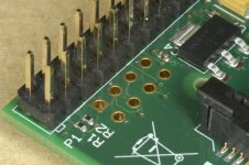
I'm not using Molex KK, just simple headers like the ones in the attached picture, but used in pairs. They've been fine on the previous versions of the boards.
There are many things that might be done differently. I recognise that some people, myself included, aren't comfortable with smd soldering. It's a protoyping exercise and if my approach enables a few more people to try out the no-dac approach to DSD playback then why not. There's nothing to stop the approach being iteratively optimised. So for now I've deliberately kept things simple in line with my experience/knowledge/time.
The bottom of the boards are ground planes.
I didn't set out to run a GB, I just offered the spare PCBs, however, there was a good level of interest and I'm happy to help with the supply of a few PCBs but I don't want to attract any more interest at this time because I know the effort that is involved with this sort of exercise. If, as a moderator, you're happy to leave it as it is I would prefer it.
Ray
The pads are 0.1" but do the more or less standard Molex KK connectors or similar 0.1" ones fit in the available space physically ? I don't think so.
I'm not using Molex KK, just simple headers like the ones in the attached picture, but used in pairs. They've been fine on the previous versions of the boards.
I would have gone SMD on such a simple and small board to allow for onboard PSUs (read: added versatility). Some GND pads at the bottom of the board could be added to solder a metal GND shield under the PCB to avoid nasties.
There are many things that might be done differently. I recognise that some people, myself included, aren't comfortable with smd soldering. It's a protoyping exercise and if my approach enables a few more people to try out the no-dac approach to DSD playback then why not. There's nothing to stop the approach being iteratively optimised. So for now I've deliberately kept things simple in line with my experience/knowledge/time.
The bottom of the boards are ground planes.
Since this seems to develop to a Group Buy it is better to add a new thread in that section with all necessary details. You will reach more people with your design too. It also avoids many questions that can be annoying when answering the same stuff for the third time. All info in the first post with design goals, needed materials and practical use etc. In my experience members will update regularly with their experiences and useful additions. Please don't underestimate the work involved with a GB.
I didn't set out to run a GB, I just offered the spare PCBs, however, there was a good level of interest and I'm happy to help with the supply of a few PCBs but I don't want to attract any more interest at this time because I know the effort that is involved with this sort of exercise. If, as a moderator, you're happy to leave it as it is I would prefer it.
Ray
Attachments
That's OK Ray but please note I am not a moderator. I once was one.
So, should I add you to the list?
I've made some adjustments to my prototype flip-flop board so that the relay and led are triggered directly from the JLSounds header pins without the TLP185 isolators - the switching works without a problem. The test reflects the configuration of the latest draft of the boards so that's good.
Without building it I haven't tested Fabio's mute delay circuit but it works for him and he has reviewed the circuit so I will accept that it is OK.
If we accept that level of testing we're ready to go with ordering the PCBs.
I have received some advice that I should get payment up front rather than committing my own funds; it seems that GBs are notorious for people not following through on their initial interest and I have no need for a lot of spare PCBs! I understand that and, whilst in an ideal world I would prefer not to, I am going to take the advice. I will therefore PM everyone on the list with PayPal instructions. Please either send the payment or let me know that you are no longer interested so that people aren't kept waiting unduly. I'm not entirely comfortable with taking money and then keeping people waiting for several weeks but I trust you chaps will understand.
As of this point I'm not going to take any more requests until this pans out but people are welcome to express an interest and I'll try to slot them in if anyone falls by the wayside.
Onwards
Ray
- Home
- Source & Line
- Digital Line Level
- The Best DAC is no DAC