A word of caution, though: This setup requires that the output be switched off (I short the output pins after the resistors with a relay) when there's no DSD signal. Otherwise the Q and Qnot pins will remain constant at either a high or a low level which quickly will give about Vcc on the output. With the Amanero board I have made this work, albeit not yet perfectly as I still get some rather loud clicks on the output. But maybe the JLSound's board is better here?
Curious to check my understanding of the issue described. I''ve been referring to this 74HC74 datasheet;
http://www.farnell.com/datasheets/1967651.pdf
At the top of page 2 there is a function table. Is the issue described above the same as that shown in row 3 of the table?
If so, it looks as though it could be resolved by turning PRE or CLR to high (which I take to mean a voltage is applied to the relevant pin(s)) whenever there is no DSD data?
I'm interested because my mute board shorts the output of the USB board (pins 13 & 14 on the JLSounds USB board) to ground whenever the codec is reset (pin 7), which would be ineffective in the situation described above because it is before the 74HC74.
More generally, Using my JLSounds USB board with my muting arrangement and consistency of playback material (only ever DSD256) I am not experiencing any pops or clicks.
Ray
LEON,
Thank you for reply though ECL never saturate thus got speed spending power consumption.
FIR filter is just a filter. you can build analog post filter with enough rejection without FIR filter but it must be higher order than with FIR filter.I think.In addition inherently FIR have no nonlinearlity other than 1bit DACs have.
double differential architecture is to minimize supply current ripple.Think , if 74HC74 Q output have 10kohm load and Qbar is no load, load current will 0.5mA at 1state and 0mA at 0state which fast ripple current flows from supply so supply voltage is messed.
But if Qbar have same 10kohm load ,0.5mA load current also flows at 0state then supply current ripple is minimized.
74HC74 DAC's reference is supply rail itself you know, so it must be clean.
duty : in 1bit DAC each "1" must have same V t square.but in reality each pulses have limited propagation delay and slew rate. If two or more "1" continues first 1 have positive edge but next dont ,last 1 have negative edge but others dont. so to keep each 1 have same V t square all 1 should have positive and negative edge thus 1 duty is lowered.
FF output schematic.
Hi all,
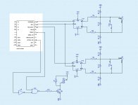
I've now drawn up a schematic of the FF output I use - without a coupling capacitor or transformer - please see attachment.
As I mentioned earlier I use the Amanero combo384 board and since this is also used with Signalyst's DSC-1 I have taken the liberty of copying the DSC-1's muting circuitry. One difference though is that to avoid having a relay in the signal path I've inverted the logic output (from an AND to a NAND) and now short the output when the signal is not DSD or there is a sample rate change.
Please note that the output capacitors from the resistors is either the 15 nF (preferred) or the 33nFs.
However, I do have some rather nasty clicks/pops when shifting tracks - something I have looked into and it seems that the "mute" from the Amanero does not work as intended. It more or less is constantly at VCC - I'm thinking that I may have inadvertently damaged these gates from the Amanero board and so it may not be that simple to amend
To my ears the sound of this circuitry in some respects is second-to-none compared with what I've otherwise heard. Especially when it comes to "speed", tonal nuance, and imaging it's quite remarkable. So quick and with an equal attention to everything. And the ability to shift character as the music seems to change ... I am a little unsure though whether this is due to the DSD principle as such or it's because the PSU and the clocks are probably very good (clocks almost feed directly into the FFs and the amanero is fed from the same clocks).
Anyway, this is the schematic - hope it helps clarify how my DSD DAC is made.
Cheers,
Jesper
Hi all,
I've now drawn up a schematic of the FF output I use - without a coupling capacitor or transformer - please see attachment.
As I mentioned earlier I use the Amanero combo384 board and since this is also used with Signalyst's DSC-1 I have taken the liberty of copying the DSC-1's muting circuitry. One difference though is that to avoid having a relay in the signal path I've inverted the logic output (from an AND to a NAND) and now short the output when the signal is not DSD or there is a sample rate change.
Please note that the output capacitors from the resistors is either the 15 nF (preferred) or the 33nFs.
However, I do have some rather nasty clicks/pops when shifting tracks - something I have looked into and it seems that the "mute" from the Amanero does not work as intended. It more or less is constantly at VCC - I'm thinking that I may have inadvertently damaged these gates from the Amanero board and so it may not be that simple to amend
To my ears the sound of this circuitry in some respects is second-to-none compared with what I've otherwise heard. Especially when it comes to "speed", tonal nuance, and imaging it's quite remarkable. So quick and with an equal attention to everything. And the ability to shift character as the music seems to change ... I am a little unsure though whether this is due to the DSD principle as such or it's because the PSU and the clocks are probably very good (clocks almost feed directly into the FFs and the amanero is fed from the same clocks).
Anyway, this is the schematic - hope it helps clarify how my DSD DAC is made.
Cheers,
Jesper
Attachments
Thanks Jesper.
I notice you apply Vcc to PRE and CLR; did you have any thoughts on my earlier post about this?
Based on the clues in your previous post and general enthusiasm for this direct-DSD approach I got thinking over the weekend and put together my own schematic, which is very similar to yours;
I got to thinking about how flexible this might be so I've worked on a PCB layout intended to be a flexible 'all in one' board with a flip-flop, four LP filters and two relays so. with the use of wire links it can;
I've also included a circuit that turns on an LED when DSD material is detected. I've attached a screenshot. It's still designed to sit on the header pins of the JLSounds board and is just 50mm square, which is important to keep the cost of fabrication low.
I'm interested in any constructive feedback.
Ray
I notice you apply Vcc to PRE and CLR; did you have any thoughts on my earlier post about this?
Based on the clues in your previous post and general enthusiasm for this direct-DSD approach I got thinking over the weekend and put together my own schematic, which is very similar to yours;
An externally hosted image should be here but it was not working when we last tested it.
I got to thinking about how flexible this might be so I've worked on a PCB layout intended to be a flexible 'all in one' board with a flip-flop, four LP filters and two relays so. with the use of wire links it can;
- be a very simple single-ended LP filter with muting (but no DC blocking cap).
- produce balanced outputs, via a flip flop, for passing to off-board transformers (or TVCs) or LP filters. The outputs can mute.
- produce balanced outputs, via a flip flop, with onboard LP filters and muting.
I've also included a circuit that turns on an LED when DSD material is detected. I've attached a screenshot. It's still designed to sit on the header pins of the JLSounds board and is just 50mm square, which is important to keep the cost of fabrication low.
An externally hosted image should be here but it was not working when we last tested it.
I'm interested in any constructive feedback.
Ray
Hi Ray,
You are welcome ...
Yes, my reason for applying Vcc to PRE (not) and CLR (not) is that when I used Mute & DSDOE to pull these two terminals to GND level I had a significant DC burst both grounding PRE & CLR and when releasing the two pins. When CLR & PRE are at VCC level the outputs reflect the data and clk states.
And then a couple of comments on your design:
1. I use two flip-flops with equally short distances to clk and data. The reason for this is the "ground-bounce" phenomena - i.e. inductive resistance in the ground connection. My guess would be that having two channels in the samme IC will reduce channel separation significantly.
2. It doesn't look as if you have any decoupling capacitor on the 74HC74? Hmmm... IMHO the PSU is key to such a design so I personally would boost it quite some ...
3. The digital signal on the outputs from the FF is very high frequency (close to "real" square waves) which means that the capacitors used to decouple the output after the resistors most likely should be very small and HQ - and connected with very short traces (as short as practically possible) to the output resistors (as to keep inductive resistance low). Maybe two different capacitors with different characteristics.
The GND IMHO preferably should be a plane (at least a wide trace connection) in order to avoid GND radiation and GND inductance.
4. Again due to the high frequency content I would move the output capacitors outside of the radiation field of the tracks + resistors (straight and close wires from the FF & resistors straight on from there - followed by the capacitor at a 90 degrees angle from the resistors).
5. Unless someone suggests that the capacitor for some reason should not be connected between the output resistors that would be my main suggestion (it would eliminate the GND return path) ... ?
6. If you connect the two relays to GND I reckon that due to slight timing differences one relay may short slightly prior to the other which could lead to clicks or pops.
Also the GND level only rarely is the level the DSD DAC is at - at any given point in time. If instead the relay shorts the two outputs (i.e. after the two resistors) there's no timing difference (one relay only) and the relay shorts the DSD DAC to the current averaged level of the outputs (don't know if this last point matters, though).
Additionally - and I forgot to insert this in my schematic - I would add a small resistor in series with the relay. If e.g. the output capacitor at any given time is charged to say 3 VDC it will discharge more or less instantaneously through the relay - most likely causing the current to exceed what the relay is specified at. I personally use a 0.33 ohms resistor and an 8A (quality - 50 mohms resistance) relay. This will give a damping of about 50 dB of any clicks or pops - in practice this is low enough for me. If the output resistors are changed other values may give other results.
No further comments - hope (some of) this helps.
Cheers,
Jesper
You are welcome ...
I notice you apply Vcc to PRE and CLR; did you have any thoughts on my earlier post about this?
Yes, my reason for applying Vcc to PRE (not) and CLR (not) is that when I used Mute & DSDOE to pull these two terminals to GND level I had a significant DC burst both grounding PRE & CLR and when releasing the two pins. When CLR & PRE are at VCC level the outputs reflect the data and clk states.
And then a couple of comments on your design:
1. I use two flip-flops with equally short distances to clk and data. The reason for this is the "ground-bounce" phenomena - i.e. inductive resistance in the ground connection. My guess would be that having two channels in the samme IC will reduce channel separation significantly.
2. It doesn't look as if you have any decoupling capacitor on the 74HC74? Hmmm... IMHO the PSU is key to such a design so I personally would boost it quite some ...
3. The digital signal on the outputs from the FF is very high frequency (close to "real" square waves) which means that the capacitors used to decouple the output after the resistors most likely should be very small and HQ - and connected with very short traces (as short as practically possible) to the output resistors (as to keep inductive resistance low). Maybe two different capacitors with different characteristics.
The GND IMHO preferably should be a plane (at least a wide trace connection) in order to avoid GND radiation and GND inductance.
4. Again due to the high frequency content I would move the output capacitors outside of the radiation field of the tracks + resistors (straight and close wires from the FF & resistors straight on from there - followed by the capacitor at a 90 degrees angle from the resistors).
5. Unless someone suggests that the capacitor for some reason should not be connected between the output resistors that would be my main suggestion (it would eliminate the GND return path) ... ?
6. If you connect the two relays to GND I reckon that due to slight timing differences one relay may short slightly prior to the other which could lead to clicks or pops.
Also the GND level only rarely is the level the DSD DAC is at - at any given point in time. If instead the relay shorts the two outputs (i.e. after the two resistors) there's no timing difference (one relay only) and the relay shorts the DSD DAC to the current averaged level of the outputs (don't know if this last point matters, though).
Additionally - and I forgot to insert this in my schematic - I would add a small resistor in series with the relay. If e.g. the output capacitor at any given time is charged to say 3 VDC it will discharge more or less instantaneously through the relay - most likely causing the current to exceed what the relay is specified at. I personally use a 0.33 ohms resistor and an 8A (quality - 50 mohms resistance) relay. This will give a damping of about 50 dB of any clicks or pops - in practice this is low enough for me. If the output resistors are changed other values may give other results.
No further comments - hope (some of) this helps.
Cheers,
Jesper
Last edited:
1. I use two flip-flops with equally short distances to clk and data. The reason for this is the "ground-bounce" phenomena - i.e. inductive resistance in the ground connection. My guess would be that having two channels in the samme IC will reduce channel separation significantly.
So question #1, what flip-flops do you use. There are lots available so easier to get a recommendation for one that is known to work.
Also. I think I can see a way of using only one relay but retaining the flexibility I set out to achieve.
Work to do.
Ray
at last
after read about this DSD on the net, I found only talk about the dsd only filter with no DAC but not implementation, until I got here, thanks.
I buy this XMOS U8 that generates DSD256.
I want to build simple circuit to compare DSD to R-2R and sigma delta technology.
Do I have MUTE function in this XMOS?
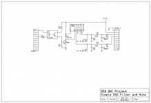
This is the final LPF? my load is tube preamp
Can I live with NO MUTE function?
Thanks all
after read about this DSD on the net, I found only talk about the dsd only filter with no DAC but not implementation, until I got here, thanks.
I buy this XMOS U8 that generates DSD256.
I want to build simple circuit to compare DSD to R-2R and sigma delta technology.
Do I have MUTE function in this XMOS?
This is the final LPF? my load is tube preamp
Can I live with NO MUTE function?
Thanks all
Attachments
Hi Ray,
Potato semi due to their allegedly low PSU noise. It think it's called PO74G74 - dual FF.
Cheers, Jesper
So question #1, what flip-flops do you use.
Potato semi due to their allegedly low PSU noise. It think it's called PO74G74 - dual FF.
Cheers, Jesper
at last
after read about this DSD on the net, I found only talk about the dsd only filter with no DAC but not implementation, until I got here, thanks.
I buy this XMOS U8 that generates DSD256.
I want to build simple circuit to compare DSD to R-2R and sigma delta technology.
Do I have MUTE function in this XMOS?
This is the final LPF? my load is tube preamp
Can I live with NO MUTE function?
Thanks all
I am not familiar with that USB board so I don't know if it has a pin out suitable for triggering the mute circuit. The schematic you included references the header pins of the JLSounds USB board and I suggest you cross reference the documentation for the two boards to see if yours has the capability.
You might be able to live without mute but I couldn't. There is a risk of very loud pops/clicks from this DSD replay approach and it is possible that you could damage something. The mute circuit helps with this noise issue.
I don't know if you would be able to drive your tube amplifier directly with this solution, there are just too much variations of amplifier inputs out there to take a view. What I can say is that the output from this DSD approach is lower than a typical source component, such as a CD player. You'll have to suck it and see.
Incidentally, your USB board doesn't generate DSD256 but it might be capable of processing it. You need to pass DSD data to it, either from DSD files or upsampled from some other format. I say it might be capable of DSD256 because that will be dependent on what computer OS you interface to and whether the drivers etc. support it.
If you're interested in a small PCB that implements the schematic drop me a PM and we may be able to sort something out - check out post #355 for more information.
Anyway, good luck and if you go ahead with the project I hope you enjoy the results as much as I am.
Ray
Is it worth considering other xmos cards instead of jlsounds one? I guess anything with dsd256 output can be used?
Sent from my Nexus 6 using Tapatalk
Yes, broadening the selection of suitable devices is no bad thing.
What I would say is that general experience seems to suggest that a specification that says DSD256 capable doesn't necessarily translate into a DSD256 solution because of driver compatibility etc.
Hi Ray,
Potato semi due to their allegedly low PSU noise. It think it's called PO74G74 - dual FF.
Cheers, Jesper
Available here: 7474 G Series GHz TTL CMOS Logic IC 14PIN SOIC Qty 1 | eBay
It's in use in my S03 board by Acko, works very well.
Yes, I was looking at that too; I think I'll stick with this one for now as I can use the high quality low noise 5V supplies already in place.
SN74HC74N - TEXAS INSTRUMENTS - LOGIC, DUAL D-TYPE FLIP-FLOP, 14DIP | Farnell element14
I've been reworking the PCB layout to reflect Jesper's feedback. One thing I keep thinking about is SMD components, I don't like hand soldering these as I'm a bit ham-fisted but you can keep everything very compact. Through-hole parts aren't as scary to work with. Would like to hear your views - are SMD worth the extra effort sonically?
Ray
I switched to SMD recently and not looking back. Just get a good magnifier lamp and fine point soldering iron. The most difficult part are SMD chips, and most of them don't exist in any other package anyway. I don't think there is a sonic difference.Yes, I was looking at that too; I think I'll stick with this one for now as I can use the high quality low noise 5V supplies already in place.
SN74HC74N - TEXAS INSTRUMENTS - LOGIC, DUAL D-TYPE FLIP-FLOP, 14DIP | Farnell element14
I've been reworking the PCB layout to reflect Jesper's feedback. One thing I keep thinking about is SMD components, I don't like hand soldering these as I'm a bit ham-fisted but you can keep everything very compact. Through-hole parts aren't as scary to work with. Would like to hear your views - are SMD worth the extra effort sonically?
Ray
I´m working on LiFePO4 supplies (one +5VUSB for self powered feature and one for +5V for isolator USBtoI2S and +5V for flip/flop).
Soshine batteries with integrated BMS looks nice (26650, 3.6V@3.2Ah) but they need single charging: 2x 3S package. Otherwise, 2x 12V pack with BMS (waste a lot of energy with LDO) and two charger. LDO should be ADM one.
Jean-Paul
Soshine batteries with integrated BMS looks nice (26650, 3.6V@3.2Ah) but they need single charging: 2x 3S package. Otherwise, 2x 12V pack with BMS (waste a lot of energy with LDO) and two charger. LDO should be ADM one.
Jean-Paul
- Home
- Source & Line
- Digital Line Level
- The Best DAC is no DAC