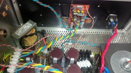
In this case, and with large caps generally in my builds, I would support the caps with some hot glue after the PCB is finished.
Have a look at the large PSU caps in the lower part of the picture (my Aleph in the process of building - sorry, I don't find a better picture at the moment):

In the case you have shown with the two Silmic caps, I would also support them with some hot glue to the PCB, not only to each other.
The amp will probably not be sent around via post or parcel service at a later point in its life, but the support would prevent damage even then.
Also, provides some damping against vibrations from transfomer or other sources ...
Best regards,
Claas
Have a look at the large PSU caps in the lower part of the picture (my Aleph in the process of building - sorry, I don't find a better picture at the moment):
In the case you have shown with the two Silmic caps, I would also support them with some hot glue to the PCB, not only to each other.
The amp will probably not be sent around via post or parcel service at a later point in its life, but the support would prevent damage even then.
Also, provides some damping against vibrations from transfomer or other sources ...
Best regards,
Claas
Attachments
Could you indicate the value of the resistor and where is soldered? thanks.

This was the recommended connection for powering an LED indicator using the Salas Shunt Reg (the white/Red wire). You could make a similar connection with the Kubota Reg. to an unused diode via.
Why are you using those big *** capacitors? I don't believe the Silmic II is of any advantage in the C1 & C2 position.
Good question. I happen to have them in my drawer. I also have four very cheap ones, but I’m reluctlant to use the cheap ones. I don’t even know the brand...
although they fit wellDear wise guys, I feel I'm always asking dumb questions, but so are my electronics... Well, I'm having problems to figure how to wire the pcb. Instead of talking nonsense, I have a little drawing of what I'm doing
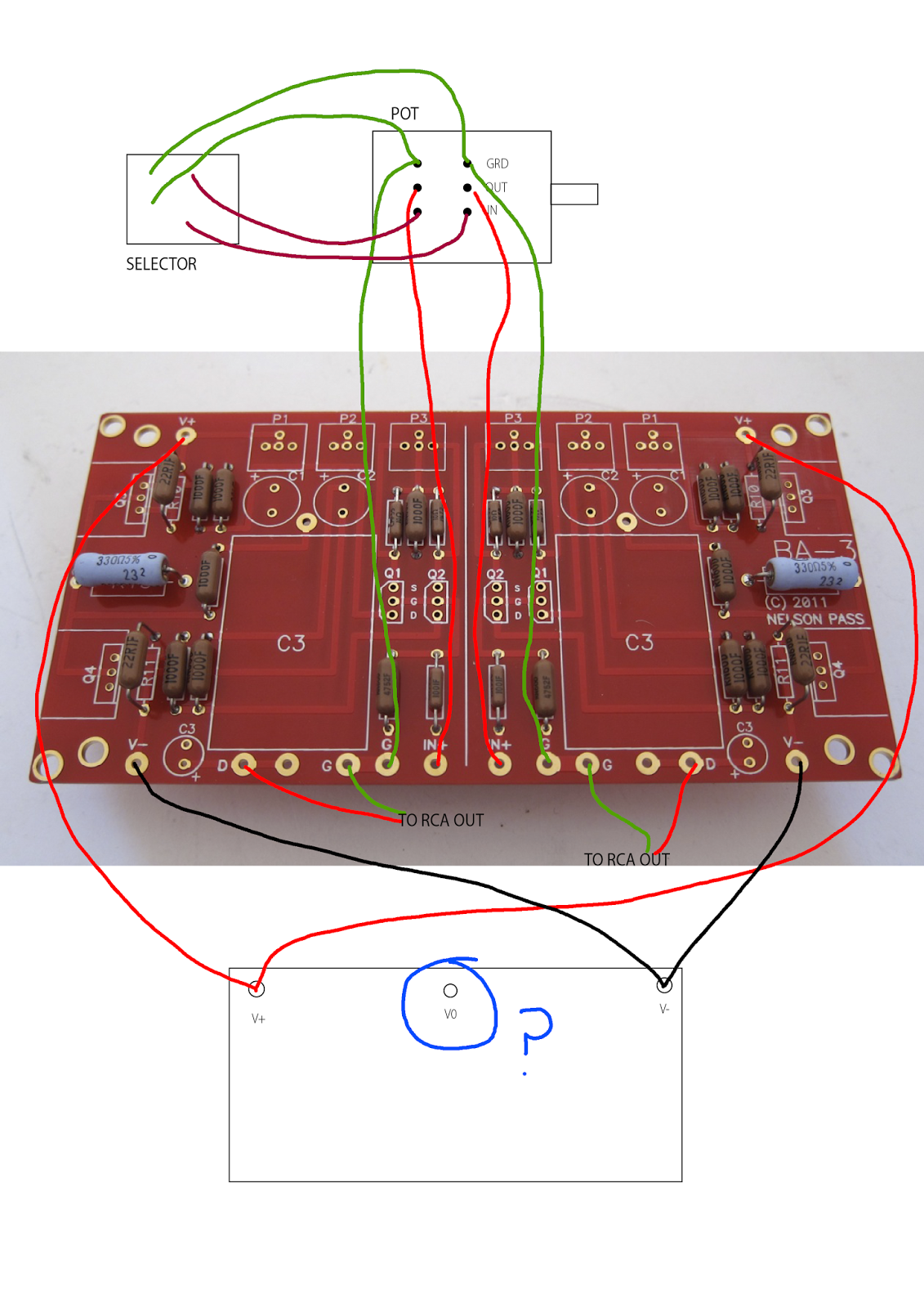
My first idea is to wire the V0 from the 317/337 also on the ground where the one from the Pot comes from, but I don't feel sure.
Many thanks!
My first idea is to wire the V0 from the 317/337 also on the ground where the one from the Pot comes from, but I don't feel sure.
Many thanks!
You are correct, neutral of your power supply should connect to ground.
If you want to use pot as volume control you should only connect input signal to this pot then short any 2 legs (besides) of the pot. Don't connect ground and output to pot.
For selector, if you want to use selector to be able to select your source - only connect the input.
If you want to use pot as volume control you should only connect input signal to this pot then short any 2 legs (besides) of the pot. Don't connect ground and output to pot.
For selector, if you want to use selector to be able to select your source - only connect the input.
So, the wiring should look like that:
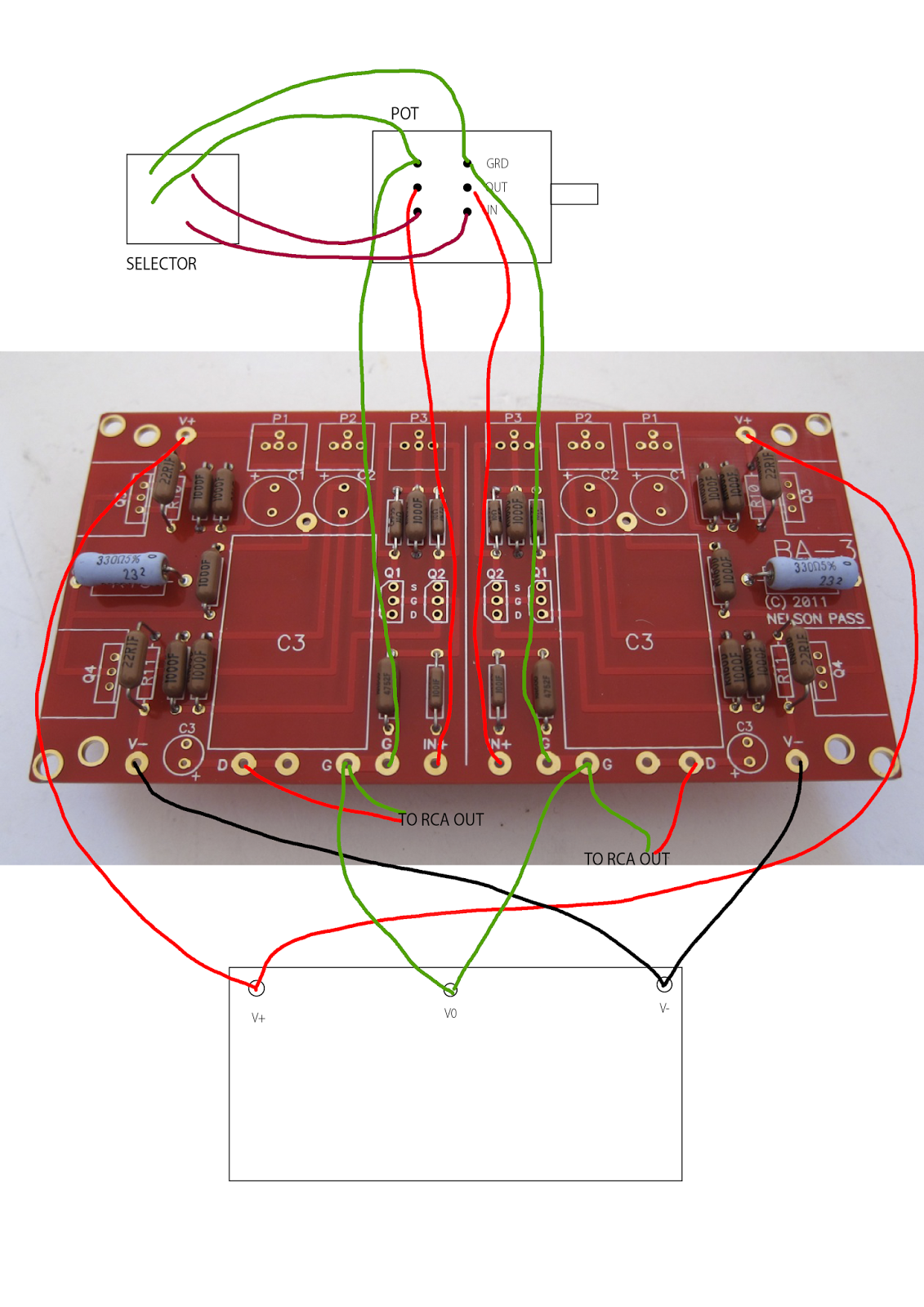
My selector is simple, so all the grounds (in spain we call them negatives) I can put them together and wire them directly to the ground in the pot and from there, to the pcb, skipping the selector, which has no ground binding post, right?
I don't know what you mean by shorting any 2 legs...
Thanks a lot.
Sorry guys, but I still need more help here. I’m about to start the bias and I have some trouble understanding. So far, my PSU works. I did the bulb test and everything was fine. The regulator is set up to 24V positive and negative. I finished soldering the rest of wires. Well pot1 and 2 I dont know if they are set to 0 ohm or not. I just turn them clockwise until click. I located R10, 11 and 12, but I don’t know which one is source resistor and I don’t know what Iq is. So I’m a bit lost there.
Also I don’t know where to measure before the capacitor. In any case, not much place there, I don’t know how to do it!
THanks a lot for your help here.
Also I don’t know where to measure before the capacitor. In any case, not much place there, I don’t know how to do it!
THanks a lot for your help here.
Do not power ON until you have proved that the two bias adjust potentiometers (p1 & p2)are set to minimum resistance.
You can measure that with the Ohms function, or continuity function of a DMM.
Set p3 to exactly mid resistance. Again you can measure this with the ohms function of a DMM.
You can measure that with the Ohms function, or continuity function of a DMM.
Set p3 to exactly mid resistance. Again you can measure this with the ohms function of a DMM.
Last edited:
Sorry guys, but I still need more help here. I’m about to start the bias and I have some trouble understanding. So far, my PSU works. I did the bulb test and everything was fine. The regulator is set up to 24V positive and negative. I finished soldering the rest of wires. Well pot1 and 2 I dont know if they are set to 0 ohm or not. I just turn them clockwise until click. I located R10, 11 and 12, but I don’t know which one is source resistor and I don’t know what Iq is. So I’m a bit lost there.
Also I don’t know where to measure before the capacitor. In any case, not much place there, I don’t know how to do it!
THanks a lot for your help here.
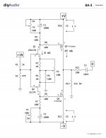
You want 1V across R10 (just like in the schematic). Thats 45ma bias.
Measure between C3 and R12 (capacitor leg that in not output to RCA) and ground for DC offset. P3 also effects DC offset so make sure it's in the middle position or where you want it before zeroing the offset. You will not be able to zero the offset entirely....the cap is there to eliminate the rest of the DC. Honestly, if you can get it stable under 100mv you are OK.
Your pots should be zeroed. You may be able to measure between the junction of V+ and R8/Q1 to verify but with the cap (C1) in there I am not sure. Remember the 100R resistor is in the path as well when taking this reading.
Attachments
Yeah, I love when you talk to me like a silly kid, cause I am in terms of electronics. I managed to make P1 and 2 0R and P3 is in the middle counting turns, couse everything is soldered and I don’t trust what I measure. I will procede to make this motherf***r rock!!
Thanks a lot guys.
Thanks a lot guys.
- Home
- Amplifiers
- Pass Labs
- The BA-3 as preamp build guide