Hi,
I spent all afternoon repairing one channel of the bootstrapped Amnesis. Lets remember this one worked OK when drivers were upgraded to the last zener biasing but cascoded exploded when a too enthusiastic power output test was performed: I had the BD139/BD140 cascodes epoxi-glued to the body of the drivers They did not withstand 40V PtP output...
I saw no signs of oscillation then.
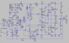
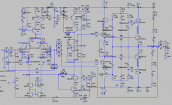
I had to change the physical position and orientation of the new cascoded drivers on daughter boards because of the damage of the original board from the constant tweaking. After all connections, it ended up as a 3D mess No wonder it oscillates.
Remember now I have the split resistors for the CCS. After many unsuccessful efforts, I decided to go for the "double bootstrap" with shared bootstrap cap and forget about methodical, step by step progression of listening tests, due to my version being so susceptible to oscillation, perhaps EMI? When I completed the "double bootstrap with shared capacitor" (150u/50V, of which I have plenty around) the amp transformed into a perfect oscillator, meaning a very neat wave of more than 10MHz was observed, very precise trace. I interpreted this as a good sign. Fortunately, the 22nF from base to ground of the cascodes, on both sides, cured the oscillation. Maybe not the perfect solution but still effective to make preliminary listening mono tests. I will not extend into these until stereo is done. All I'll say is that it sound as a LTMD amp, clean, open and dynamic. I tortured it with 35V PtP output swing (Bassy Jazz) and no alarm sign was detected. Heat-sinks for the drivers are cool.
I hope a clean new build will be less prone to oscillation. More experimentation and thought about causes and cures will follow.
Cheers,
M.
I spent all afternoon repairing one channel of the bootstrapped Amnesis. Lets remember this one worked OK when drivers were upgraded to the last zener biasing but cascoded exploded when a too enthusiastic power output test was performed: I had the BD139/BD140 cascodes epoxi-glued to the body of the drivers
They did not withstand 40V PtP output...I saw no signs of oscillation then.
I had to change the physical position and orientation of the new cascoded drivers on daughter boards because of the damage of the original board from the constant tweaking. After all connections, it ended up as a 3D mess
No wonder it oscillates. Remember now I have the split resistors for the CCS. After many unsuccessful efforts, I decided to go for the "double bootstrap" with shared bootstrap cap and forget about methodical, step by step progression of listening tests, due to my version being so susceptible to oscillation, perhaps EMI? When I completed the "double bootstrap with shared capacitor" (150u/50V, of which I have plenty around) the amp transformed into a perfect oscillator, meaning a very neat wave of more than 10MHz was observed, very precise trace. I interpreted this as a good sign. Fortunately, the 22nF from base to ground of the cascodes, on both sides, cured the oscillation. Maybe not the perfect solution but still effective to make preliminary listening mono tests. I will not extend into these until stereo is done. All I'll say is that it sound as a LTMD amp, clean, open and dynamic. I tortured it with 35V PtP output swing (Bassy Jazz) and no alarm sign was detected. Heat-sinks for the drivers are cool.
I hope a clean new build will be less prone to oscillation. More experimentation and thought about causes and cures will follow.
Cheers,
M.
The magic of bootstrapping...apart giving more headroom, less current is needed at the CCSs to achieve the same swing, but THD can be lower at some point and we can play with values to achieve both.
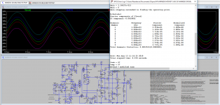
See how the DC voltage at the bootstrap node goes up and so does AC swing (+/-60 or more) depending on value of resistors. This curves are with 1.3VAC input signal. near clipping. We are learning...we are learning...
I have to simulate if one bootstrapped-CCS can feed both voltage sources...
See how the DC voltage at the bootstrap node goes up and so does AC swing (+/-60 or more) depending on value of resistors. This curves are with 1.3VAC input signal. near clipping. We are learning...we are learning...
I have to simulate if one bootstrapped-CCS can feed both voltage sources...
Attachments
Last edited:
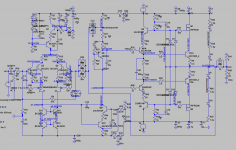
Two more variants:
1) CCS-VAS with double bootstrap and with "improved" bypassing.
2) Double-shared bootstrap. Apparently the output cascodes doesn't care where the current comes from...less parts.
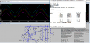
The CCS-VAS amps always show more THD (5k to 20k) than the bootstraped VAS amps.
1) CCS-VAS with double bootstrap and with "improved" bypassing.
2) Double-shared bootstrap. Apparently the output cascodes doesn't care where the current comes from...less parts.
The CCS-VAS amps always show more THD (5k to 20k) than the bootstraped VAS amps.
Attachments
Hi Max,
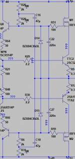
I had been looking at similar output stage simplifications. For your second circuit, you don't need to parallel the zeners, so D14 and D15 can be removed.
Also something that logically makes sense is to place a small capacitor across the zerers say about 220n this provides stabilisation and a resurve of currnet should the cascodes need it.
I think you observed yesterday that output stage cascode resistor values are rather low, I think they are supplying around 24mA, perhaps we could reduce this to around 12mA a reduce loading of the amplifier.
See attached.
Regards,
Symon
Attachments
Hi Max,
I had been looking at similar output stage simplifications. For your second circuit, you don't need to parallel the zeners, so D14 and D15 can be removed.
Yes, I know. I only wished to add more current handling capability in case of something weird happening. In my repair of the bootstrapped amp I noticed that the zeners for the driver's cascodes (1A) were either lower voltage or behaving like a capacitor: damaged.
Also something that logically makes sense is to place a small capacitor across the zerers say about 220n this provides stabilisation and a resurve of currnet should the cascodes need it.
I think you observed yesterday that output stage cascode resistor values are rather low, I think they are supplying around 24mA, perhaps we could reduce this to around 12mA a reduce loading of the amplifier.
See attached.
Regards,
Symon
OK. Like a bootstrap for the gates/bases...
Easy to try.
I tried the same but connected to rails. Not good.
With some arrangements there was a small peaking at around 7MHz.
I believe I tested even 7mA. I can test lower current for the cascodes CCS' but THD starts to climb.
I have to improve the bypassing of the input and VAS section of my CCS-loaded VAS amp as per our last plan. Last night I increased R8 to 33K and I tend to think the sound is a bit cleaner, but of course, the biggest improvement shall come from the other mods.
But tomorrow I will have to repair the other bootstrap. I hope I have time.
Many thanks for your invaluable collaboration,
M.
PS: I believe the bootstrap amp does not need the "Baker clamp", the diode parallel to Miller cap...
Last edited:
Hi Max,
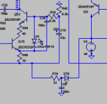
I've been looking at the VAS stage and I think the grounding could be improved, see below.
Also after playing with the simulation, I think two pole compensation looks promising way to improve phase margin and reduce distortion.
Regards,
Symon
I've been looking at the VAS stage and I think the grounding could be improved, see below.
Also after playing with the simulation, I think two pole compensation looks promising way to improve phase margin and reduce distortion.
Regards,
Symon
Attachments
Hi Max,
I've been looking at the VAS stage and I think the grounding could be improved, see below.
OK. I see what you mean.
I have to study again that articles about current sources.
Also after playing with the simulation, I think two pole compensation looks promising way to improve phase margin and reduce distortion.
Regards,
Symon
Well, that one would be too much for me. Send some ideas.
I'll have to study this topic.
About the current for the cascode's shared CCS, 2K resistors give around 8,2mA. Going higher like 3K also works but my LTspice takes more time to give results and I don't like when that happens...could mean that something is odd...
The caps parallel zeners work on paper. They do not take away a small peaking (of a fraction of uA) on the gate currents for the MOSFET cascodes...
I like that we are combining old tricks that give something for almost nothing
Cheers,
M.

Hi Max,
attached is a modified simulation with an alternative compensation.
The capactitor on the main feedback resistor creates lead compensation,
which works in simulation, but might cause oscilation in real world.
So experiment with care.
- Symon
attached is a modified simulation with an alternative compensation.
The capactitor on the main feedback resistor creates lead compensation,
which works in simulation, but might cause oscilation in real world.
So experiment with care.
- Symon
Attachments
Hi Max,
attached is a modified simulation with an alternative compensation.
The capactitor on the main feedback resistor creates lead compensation,
which works in simulation, but might cause oscilation in real world.
So experiment with care.
- Symon
Thanks dear Symon. I'll try later. I can't simulate it now.
Yesterday, I spent several hours repairing the right channel of the bootstrap VAS amp. Briefly, this one doesn't like the shared bootstrapped CCS for the drivers and output cascodes, in various shapes: HF oscillation at negative peaks, again.
The last resort was to keep simple zener + R biasing for the outputs and bootstrap CCS for the zener biasing of the drivers, AKA "double bootstrap"
So, the left channel has shared bootstrap for the biasing circuit of the drivers + outputs cascodes and the right channel has only bootstrapped the drivers not a perfect technical answer yet but I least I could make my late night, freezing climate, outdoors listening tests. I could not detect obvious differences between channels in these precarious conditions. I would risk the opinion that the bootstrapped drivers' cascodes makes the amp even more dynamic; the attacks are still more violent. As I said, I am not a big fan of guitar but I use "Entre dos Aguas" from Paco de Lucía, which allows to evaluate the impact of heavy string plucking and body resonance.
This amps has "concentrated energy" in time domain. Next, I have to make the "Triple boostrap" and see if this separated bootstrap strategy is better tolerated. The differences between channels could be related to the physical layout of my heavily modified board or to differences between active devices,,,
I would be ashamed to show pics of this mess...Anyway, another trick that I could use is to take the R//L output filter out of the PCB and see what happens, like it is on my CCS-VAS amp.
Talking about the CCS-VAS amp, the "modern sounding" one, I have yet to perfect the bypassing for the first stages (no bootstrap on this one) but the micro-detail is coming out: you know when the violin bow is too light on the strings of a sensitive violin, it makes a "nervous" sound before notes. In real life you only hear it when you are near the violin and this is seldom heard in recordings. Well, I can hear this phenomenon in several recordings form different players with this amp.
Cheers,
M.
Hi Max,
I realise I forgot something while running the simualtions so while they seem stable dynamically I need to run tests to check phase behaviour ...
I've been checking further and the two pole compensation increases the gain at 10Khz, and the faster roll off give a 25 - 30 degree phase margin. and we have about 10Db gain margin.
Capacitor C15 generally appears to improve distortion, but as noted above in practice this could lead to instability. Bob Cordel recommends avoiding these. But in this case it appears to work with a reasonably large value that isn't very critical, usually these capacitors are just a few pF, so someting to pllay with.
I also had a throught about current limiting, the MOSFET cascodes probably provide current limiting which is selectable using different zener voltages. So under fault conditions just need fuses to kill the power.
Regards,
Symon
Hi Max,
I realise I forgot something while running the simualtions so while they seem stable dynamically I need to run tests to check phase behaviour ...
I've been checking further and the two pole compensation increases the gain at 10Khz, and the faster roll off give a 25 - 30 degree phase margin. and we have about 10Db gain margin.
Capacitor C15 generally appears to improve distortion, but as noted above in practice this could lead to instability. Bob Cordel recommends avoiding these. But in this case it appears to work with a reasonably large value that isn't very critical, usually these capacitors are just a few pF, so someting to pllay with.
I also had a throught about current limiting, the MOSFET cascodes probably provide current limiting which is selectable using different zener voltages. So under fault conditions just need fuses to kill the power.
Regards,
Symon
Hi Symon,
Capacitor parallel R feedback was tried (5 to 15pF) at an earlier stage and proved to increase oscillation tendency. I don't quite remember which version of the amp it was. Oscillation, I suspect, is due to either layout problem, or to some sort of local feedback (Colpits) or other
Two pole compensation is a technique with which I don't have any experience and I would not feel comfortable trying it, if the amp starts doing crazy things
Today I will try to experiment with "triple bootstrap". Wish me luck.
Oh! I forgot to mention that always the trick that halts negative peaks oscillation has been bypass cap (this time 150n) from drivers' cascode base to ground, not to output. I did not try RC, which was recommended by the creator of Ovation amp (who is a member but whose nickname I don't know) for VHF oscillation on his amp. Worth a try IMHO.
Cheers,
M.
Yesterday, only listening session and a barbeque party took place
Creedence's "The Midnight pecho" and things like that.
No upgrades.
Today, duty.
I will anticipate that the board without the bootstrapped output cascode has less focus and less depth of images. Probably tomorrow I will be in position of fully state the former...and probably also will declare maxlorenz' rules to musical reproduction.
Cheers,
M.
Attachments
Hi Max,
the power resistors for bootstrapping require more board space for layout.
Which power resistors (brand, seize) do you recommend.
Can these resistors be mounted vertically or horizontally one upon the other (with 2-3mm distance to the PCB).
Can a few resistors 0.25W / diodes be mounted on the solder side to save board space or trace length.
Hi Max,
the power resistors for bootstrapping require more board space for layout.
Which power resistors (brand, seize) do you recommend.
Can these resistors be mounted vertically or horizontally one upon the other (with 2-3mm distance to the PCB).
Can a few resistors 0.25W / diodes be mounted on the solder side to save board space or trace length.
Hi dear JOSI1,
Yesterday I worked a little on the output. First one side "shared bootstrap", that is only one bootstrap (2 resistors per polarity) and the other side "triple bootstrap" (four resistors per polarity) and some listening tests were performed. I had to bypass again the bases of the drivers' cascode. See below. I had the feeling that the "shared" was a bit loose on the bass and less focused as I went to upgrade it for the "triple", which was easier to stabilize, meaning getting rid of the oscillation on peaks. This was done with 27R in series with 100-150nF at the bases of the cascode T. But now I found the article by the creator of the Ovation amp (I believe he is Bonsai; sorry if I'm wrong) where he deals with the same problem but at input. See attached. I will upgrade as he advices for there is still a low grade VHF oscillation/noise that stops when I pause the source.
The problem I did not preview is that, the zener's leads being very long, I solder them in different lengths to the bases, meaning different parasitic inductances.
With 32V PS, I use 3X 0.6W resistors for bootstrap without problems, Though higher wattage can lead to less noise. I think 2W will be more than enough. As for brands, I don't have an opinion yet. I suppose any good quality metal film would be OK...
Resistors can be located underside. No problem. Due to different (unpredictable) inductances, it is better to plan for the "triple" and then taste what configuration gives better results.
They can be piggy-backed but horizontally to avoid they acting as antennas.
The trick is to place the zener (or damper R-bypass capacitor; see attachment) as near as possible from cascode's base.
Cheers,
M.
Attachments
Guys, I made another strategic error: I stopped reading Dr. Kolinummi's book just before it gets interesting (for this project, I mean) exhausted with the first part...go and get it if you haven't yet.
It reinforced me in my philosophical worry about the following, and correct me please if I'm wrong:
Our VAS is cascoded, right. A BJT in common-emitter gets help from a BJT in common-base, meaning the cascode element receives two signals: THE signal at its emitter and a DC signal, referenced to ground, which establishes the working parameters (Vbe) of the former. This transform the couple into a quimeric transistor having multiple advantages, amongst which are: it limits Early effect on the common-emitter; it allows to pick a high quality specialized transistor for this position (I am open to suggestion on the best here) due to the low working Vce it faces.
All good until now, rigth?
Well, in the driver and output sections things are a little different because the cascodes (which are cascading common-collector units, BTW) not only receive the two signals commented above but receive also a third one: a copy of the output (being EF, one can say a copy of the input) so a form of positive voltage feedback. In that way it is more like a bootstrap than like a cascode. This is not just semantic. Or we must invent another term. It is not a classic bootstrap in the sense that it does not pull-up the working voltages, like the bootstrap for the CCS part of the voltage reference for the DC bias part of the same cascodes, which works like a positive current feedback to keep the CCS properly working near ideal situation, or that is what I understood. So, what do you think about the "bootstrap" positive AC feedback connection we have here? Maybe it is helping the sense of dynamics, maybe it helps (or deteriorates) linearity...I have to read further this excellent Kolinummi book.
BTW, go and check the Ovation amp site. It's a joy to read and full of useful theoretical and practical information.
Ovation e-Amp: A 180 Watt Class AB VFA Featuring Ultra Low Distortion
Attached, two simulations with the modified (as recommended by the above site) bypassing for the cascodes, with maximum values they seem to tolerate. In case of oscillation (highly probable) lowest values that cancel all oscillation must be used.
This could be modeled and simulated beforehand but I wouldn't know hot to do it exactly.
Cheers,
M.
It reinforced me in my philosophical worry about the following, and correct me please if I'm wrong:
Our VAS is cascoded, right. A BJT in common-emitter gets help from a BJT in common-base, meaning the cascode element receives two signals: THE signal at its emitter and a DC signal, referenced to ground, which establishes the working parameters (Vbe) of the former. This transform the couple into a quimeric transistor having multiple advantages, amongst which are: it limits Early effect on the common-emitter; it allows to pick a high quality specialized transistor for this position (I am open to suggestion on the best here) due to the low working Vce it faces.
All good until now, rigth?
Well, in the driver and output sections things are a little different because the cascodes (which are cascading common-collector units, BTW) not only receive the two signals commented above but receive also a third one: a copy of the output (being EF, one can say a copy of the input) so a form of positive voltage feedback. In that way it is more like a bootstrap than like a cascode.
This is not just semantic. Or we must invent another term. It is not a classic bootstrap in the sense that it does not pull-up the working voltages, like the bootstrap for the CCS part of the voltage reference for the DC bias part of the same cascodes, which works like a positive current feedback to keep the CCS properly working near ideal situation, or that is what I understood. So, what do you think about the "bootstrap" positive AC feedback connection we have here? Maybe it is helping the sense of dynamics, maybe it helps (or deteriorates) linearity...I have to read further this excellent Kolinummi book.BTW, go and check the Ovation amp site. It's a joy to read and full of useful theoretical and practical information.
Ovation e-Amp: A 180 Watt Class AB VFA Featuring Ultra Low Distortion
Attached, two simulations with the modified (as recommended by the above site) bypassing for the cascodes, with maximum values they seem to tolerate. In case of oscillation (highly probable) lowest values that cancel all oscillation must be used.
This could be modeled and simulated beforehand but I wouldn't know hot to do it exactly.
Cheers,
M.
Attachments
OK. Quick update.
Just adding 330R gate stopper resistors from Voltage reference node to MOSFET's gate (without upgrading driver's cascode bypassing) reduced the hash of the base line to 5mV.
This supports the idea that parasitic inductance from the long leads of the zeners and etc form a Collpits...
I hope upgrading to the recommended bypass on the driver's stage cascode will kill all the gremlins.
Unfortunately, not much time for playing around.
Best wishes,
M.
More on the improved bypass.
I wired the TRIPLE Bootstrap amp much like my last .asc file shows. I can tell that the MOSFET cascode's gate doesn't like a cap attached to it! It starts oscillating at peaks even at low power. We have to keep these, probably, local feedback loops as short as possible.
With the present organization (the VAS is not optimized yet) I managed to reduce but not to eliminate the base oscillation: there are two frequencies riding together, the first at 10MHz and the second at 80MHz. Note that Ft for the 4793/1837 drivers is 70MHz...
I forgot to mention that I check with speakers connected, to save time, so there is added capacitance of speakers and probes.
When sweet music stops or pauses there is a 20mV harsh (oscillation) that lasts 2-3 seconds and then it reduces to 2,5mV on one channel and to 5mV on the other channel. This is the best I could do so far. I gave up, temporarily, and now I am making listening tests. No matter that little problem, he he, the amp sounds the best so far. It has the traits of all the previous versions: dynamics and a softness of the emission, but has better resolution and delicacy. I hope I can make that harshness disappear to listen to the full potential of the Amnesis. I plan to add or increase base stoppers everywhere...every advice is welcome.
Now I have to upgrade the CCS loaded-VAS amp (a DOUBLE bootstrap) and try to make it better than the present one. I will try to make changes to reduce path lengths and try to avoid the risk of oscillation, probably due to parasitics...
Cheers,
M.
PS: some of my power resistors and the missing IRFP arrived Maybe that will help.
I wired the TRIPLE Bootstrap amp much like my last .asc file shows. I can tell that the MOSFET cascode's gate doesn't like a cap attached to it! It starts oscillating at peaks even at low power. We have to keep these, probably, local feedback loops as short as possible.
With the present organization (the VAS is not optimized yet
) I managed to reduce but not to eliminate the base oscillation: there are two frequencies riding together, the first at 10MHz and the second at 80MHz. Note that Ft for the 4793/1837 drivers is 70MHz...I forgot to mention that I check with speakers connected, to save time, so there is added capacitance of speakers and probes.
When sweet music stops or pauses there is a 20mV harsh (oscillation) that lasts 2-3 seconds and then it reduces to 2,5mV on one channel and to 5mV on the other channel. This is the best I could do so far. I gave up, temporarily, and now I am making listening tests. No matter that little problem, he he, the amp sounds the best so far. It has the traits of all the previous versions: dynamics and a softness of the emission, but has better resolution and delicacy. I hope I can make that harshness disappear to listen to the full potential of the Amnesis. I plan to add or increase base stoppers everywhere...every advice is welcome.
Now I have to upgrade the CCS loaded-VAS amp (a DOUBLE bootstrap) and try to make it better than the present one.
I will try to make changes to reduce path lengths and try to avoid the risk of oscillation, probably due to parasitics...Cheers,
M.
PS: some of my power resistors and the missing IRFP arrived
Maybe that will help.Layout Considerations
I checked some PCB manufacturers with passable prices for a small series.
The price for a simple single layer PCB and two layer PCB with vias and solder mask on both layers is nearly the same. The price difference of
35um and 70um copper is remarkable.
Benefits of a two layer PCB
saving of jumpers (15-20)
easier layout with shorter traces (partly)
thicker power traces (2x35um)
solder components from top (e.g. power transistors mounted directly to heatsink)
Solder pads (two layer)
Usually solder pads for through hole comonents are on both layers in form
of a vias if required or not. So smaller solder pads with less risk to become detached are possible.
The other possibility would be only to use a vias if required and use a solder pad only on the bottom layer for the rest.
What do you think is the better solution for an audio design.
Solder mask
Is it possible that solder mask has a negative influence on audio quality
Thank you JOSI1 for your invaluable work.
I am not an expert but I this can be viewed from two extremes, considering this is still an experimental amplifier:
a) go for the cheapest complete option possible, considering that many changes to the wiring are still probable.
b) go for the best solution, meaning heavy copper, double sided, to allow for shorter paths, higher current, resistance to de-soldering...etc.
I am inclined to the latest one but that is because I am the the daddy
of this monster baby...lets see what others think.Let me know what is the number that makes the project PCB get a reduction in price: I might buy a big lot to make it more attractive to the public
Speaking about the TRIPLE bootstrap, I am philosophizing about how the amp can sound so good even with that multi-megaHerz harsh riding the signal?...or is it how can it sound so good thanks to the same oscillation??? Can it be a similar process to what the recording AC bias of tape does to that medium???
Allegedly, high frequency bias for tape overcomes hysteresis of the magnetic tape but tape isn't the only magnetic material on the signal path! The speaker magnet is also there at the end of it. Can HF signal bias also help with speaker magnet hysteresis???
Biasing in Magnetic Tape Recording
Since the amp is "stable", meaning that it won't go into auto-kaput mode, I will still be listening for a while this "clairvoyant" version...
PS: this is with the RDRD strings not soldered...
Cheers,
M.
- Home
- Amplifiers
- Solid State
- The AMNESIS amp: a good amplifier, like a gentleman, has no memory.