Re: IRF240s
I mean, Greg uses IRF040's which are about 60A and 65V (out of my head...) . As I am a good solder, builder, diagram reader, and not much use as a designer. I thought I could use them, judging my a 200VA trafo is good enough which more or less means he is not using the IRF040 to the fullest ;-)
Ok, I first finish my Aleph 2 hopefully this week, and then I will build the Aleph X...
Edwin
Ren Hoek said:Yes! Go for it.
I mean, Greg uses IRF040's which are about 60A and 65V (out of my head...) . As I am a good solder, builder, diagram reader, and not much use as a designer. I thought I could use them, judging my a 200VA trafo is good enough which more or less means he is not using the IRF040 to the fullest ;-)
Ok, I first finish my Aleph 2 hopefully this week, and then I will build the Aleph X...
Edwin
Hi everybody, i am getting nervous fingers watching this nice X-aleph cicuit, thank you GRollins.
I want to make one but im busy making several Pearls for my friends. I made one for me and its sounds so beautiful that everyone wants to have one too!
I use an alephL and a Aleph 3 upgraded with an aleph 30 output stage.
I started building Zen and Bride of Zen some years ago and made several different version of them allways trying to improve the sound. After a while i just had to build the alephs to get further and i really love their sound, warm and liquid with rythm and color. The aleph 30 sounds cleaner and has the real kick bass that the aleph 3 was missing.
Thank you Mr Pass for your idealism and your generous support!!
Your help rescued my ears...
The idea that my alephs could be improved with x-aleph makes me dreaming....
But then i have to build a x preamp too! Has someone thougth of it?
I am thinking of a to stage design with a toshiba 2sk389 in the input differencial stage. It should be an easier task with the great work from GRollins.
Attachments
janey,
I haven't forgotten you. Be patient. There are a number of posts I need to answer, but I've been kinda preoccupied with things like having the sheriff come out and run some bad guys off of my property, in addition to the usual Stuff and Things. UPS still hasn't delivered the 48 hour days I requested long years ago.
oliverniekamp,
I've got a preamp in the works...or you are welcome to roll your own. The one I'm doing will incorporate another strategy (not NFB) to combat distortion in addition to the X topology.
all,
I have been in communication with Nelson about the cap across the NPN question. He says that oscillation can happen, but apparently it isn't a given.
I'd like to ask rtirion and others who are simulating to try alternate parts during the course of their workups. As far as I know, Nelson is using Zetex NPNs in his commercial product. I am using Motorola (aka OnSemi) MPSA18s in mine. I have used both IRF644 and IRFP044 output devices in this circuit with no problems, but sure as rain falls down, someone's going to stick in a part from Harris, Toshiba, or Motorola and end up stubbing their toe if that's the critical part. Parts substitution is a way of life for the DIY community. For that matter, go ahead and try other IRF parts. Someone asked about the IRFP244 earlier, I believe. I'd like some help nailing down the parameters that can make this thing oscillate.
Oh, and another thing--just for fun, someone hang another couple of pairs of outputs out to the sides. See if cumulative Gate capacitance is an issue. I'd be happy to try that one here in real life, but my power supply isn't big enough to handle the load.
I'd also like to request that those who are set up for it perform a Monte Carlo analysis to further define the stability region.
Thanks.
I believe I will go ahead without the cap, but will try to make room for it on the PCB. Once all this is on a board, the environment will change and it may break into oscillation once deprived of whatever stray capacitance I've got on these push boards. If I can get by without it, I probably will, but others may need to be aware of it. In my case the load is purely resistive, albeit low (about 2.5 ohms), so I don't anticipate any difficulties in operation.
Grey
"I have been in communication with Nelson about the cap across the NPN question. He says that oscillation can happen, but apparently it isn't a given. "
"Oh, and another thing--just for fun, someone hang another couple of pairs of outputs out to the sides. See if cumulative Gate capacitance is an issue. I'd be happy to try that one here in real life, but my power supply isn't big enough to handle the load.
I'd also like to request that those who are set up for it perform a Monte Carlo analysis to further define the stability region.
Thanks. "
These were the only points that I so poorly was trying to make before all the diversions sidetracked everyone. Thanks for you exploration into this issue. I believe everyone will benefit from the knowlege and be able to apply it to not only this design but many others.
Respectfully,
H.H.
GRollins said:Oh, and another thing--just for fun, someone hang another couple of pairs of outputs out to the sides. See if cumulative Gate capacitance is an issue. I'd be happy to try that one here in real life, but my power supply isn't big enough to handle the load.
Grey [/B]
Attachments
I should finish the main circuit today. It's not really complicated. I'm looking at 20V rails and 3 pairs of devices per side. You can see a better picture at: http://www.diyaudio.com/forums/showthread.php?threadid=3840
Jam,
I don't anticipate any real problems in scaling this thing up.
Steve,
Nope. Not holding anything back. Still only one channel. Don't have a clue what I'm going to do for heatsinks. Haven't even gotten in my Caddock resistors yet. Still got 5W ceramic resistors in the circuit.
janey,
Okay, hold on to your hat. This is Uncle Bear's rule-of-thumb recipe for building an Aleph:
Step One--
Choose a target RMS wattage into your speaker. Remember that most speakers have peaks and troughs in their impedance curve, depending on frequency. Plan accordingly. Leave a little elbow room.
Step Two--
Determine what that wattage/speaker impedance works out to be in terms of voltage and current.
Step Three/a--
If you're building a normal Aleph like the original product line, multiply the voltage from Step Two by 1.6. This is your DC rail voltage. Put a + and - in front of it, and you're in business.
Step Three/b--
If you're building a bridged Aleph like the XA200, multiply the voltage from Step Two by .8.
Step Four/a--
If you're building a normal Aleph, divide your current from Step Two by two. This is your total bias current.
Step Four/b--
If you're building a bridged Aleph, multiply your current from Step Two by two. This is your total bias current for both sides of the amp.
That will get you in the neighborhood. Everything else boils down to keeping the power dissipation down to reasonable levels on the output devices, and adjusting the resistors accordingly.
G'night folks...gotta charge my batteries...
Grey
thanks Grey for your response.
so if i want 60w and drive 4 ohm load i need 12.4 V supply
rail and 7.75 A bias current.
the total disipation will be 196 W and for this i need eight power
transistors (24.5W each) or maybe 12 power transistors
(16.3 W each).
is my calculations right?
and here is one more question.
how to recalculate the source resistors?
sorry for so much questions.
janey
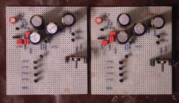
I have just finished prototyping Grey's Aleph X. I would like to thank Grey for sharing his work here and make this project available. Actually I had a good excuse to bult that amp: I wanted to prove to everybody that it's going to work in real life.")
I might as well say I did it for you, Grey.
It's just one channel but second one will be coming soon. For more detailed pictures see: http://www.diyaudio.com/forums/showthread.php?s=&threadid=3840
If that amp is really close to the production unit, which is the the best from Pass so far, and my circuit is done p2p, using exotic components and silver wiring, correct me if I'm wrong but there is a good chance I soon might be the owner of the best SS amp out there.
Attachments
janey,
My apologies, I was tired when I wrote the above (no surprise, eh? one of these days, I'll get some sleep...maybe)--had too many powers of two going through my head. Amend Step 4/b to say that the current from Step Two <i>is</i> your total bias current.
Your numbers were correct according to what I wrote; the fault is mine.
Rail= +-12.4V
Total bias (both sides)= 3.875A
Power dissipation= 96W
If you build the circuit as shown, with one pair of devices per side, your Pd per device will be a little over 23W...very reasonable. This is about where Nelson runs his output devices.
To calculate the Source resistors, divide the total bias current in half to get the amount for each side. Since I'm assuming one pair of devices per side (four total for the channel), we'll end up biasing the pair at 1.9375A (3.875A/2 sides). We'll set the voltage at .5V across the Source resistors (don't forget that you can adjust this a bit with the pots). From here, it's a simple Ohm's Law calculation: .5V/1.9375A= .258 ohms. You could go with a .27, but that would be a bit scant. You can use a .25 if you can find one, or parallel two .51 ohm resistors and end up just about perfect.
all,
For those who don't need as wide a lattitude in DC offset control (the pot under the front end differential), you can use 332 ohms for R24 and 562 ohms for R26. Leave V2= 200 ohms. This will give you tighter control over the DC offset...assuming that you don't need the latitude of the other version.
Grey
I soon might be the owner of the best SS amp out there
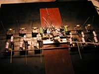
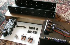
Is it done yet..... or should I hurry like hell to finish the Tex-X. I have silver wire and 0.5 ohm 1% Vishay Bulk foil source resistors and lots of Caddocks.... I hope you used 4% silver solder also! My chassis work will never compare to your's but I got a great heat sink for $13. And many parts in exchange for feeding Jocko pizza!
Is it done yet..... or should I hurry like hell to finish the Tex-X. I have silver wire and 0.5 ohm 1% Vishay Bulk foil source resistors and lots of Caddocks.... I hope you used 4% silver solder also! My chassis work will never compare to your's but I got a great heat sink for $13. And many parts in exchange for feeding Jocko pizza!
Attachments
Re: I soon might be the owner of the best SS amp out there
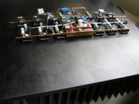
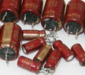
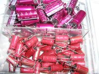
Everything looks good except for the caps. Try to improve on that. I'm not even talking about Vishay VTA56 I'm using everywhere. Actually I have a good question for you. I know you were tweaking your Aleph, what would you recommend for source resistors: Caddocks, Mills wirewounds or something else (but not too expensive). When you have to buy 24 resistors price is important. And those Vishays you see there I bought at $2 ea.
HarryHaller said:Is it done yet..... or should I hurry like hell to finish the Tex-X. I have silver wire and 0.5 ohm 1% Vishay Bulk foil source resistors and lots of Caddocks.... I hope you used 4% silver solder also! My chassis work will never compare to your's but I got a great heat sink for $13. And many parts in exchange for feeding Jocko pizza!
Everything looks good except for the caps. Try to improve on that. I'm not even talking about Vishay VTA56 I'm using everywhere. Actually I have a good question for you. I know you were tweaking your Aleph, what would you recommend for source resistors: Caddocks, Mills wirewounds or something else (but not too expensive). When you have to buy 24 resistors price is important. And those Vishays you see there I bought at $2 ea.
Attachments
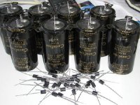
except for the caps
There was not room for my 10,000 uF 100V RIFAs. The Panasonic TSUs actually sound good in my Aleph 3 with Cerafine bypasses as I plan to do. I see you are using Panasonic (HFQs?) for the smaller value caps were I will use the Cerafines. I guess we will call it a capacitor stalemate. The Mills wirewounds are great for source resistors and that is what i would buy new. The Vishays I am going to use are over $40 a peice new and probably custom order at that. I have done some REALLY LUCKY surplus shopping as of late. If I told what I paid for the Vishays we would have a riot on our hands. I sent some to a friend and he thinks they are drop dead good sounding also. A case of when good things happen to bad people I guess. So I guess this means you are not done yet.........
There was not room for my 10,000 uF 100V RIFAs. The Panasonic TSUs actually sound good in my Aleph 3 with Cerafine bypasses as I plan to do. I see you are using Panasonic (HFQs?) for the smaller value caps were I will use the Cerafines. I guess we will call it a capacitor stalemate. The Mills wirewounds are great for source resistors and that is what i would buy new. The Vishays I am going to use are over $40 a peice new and probably custom order at that. I have done some REALLY LUCKY surplus shopping as of late. If I told what I paid for the Vishays we would have a riot on our hands. I sent some to a friend and he thinks they are drop dead good sounding also. A case of when good things happen to bad people I guess. So I guess this means you are not done yet.........
Attachments
- Home
- Amplifiers
- Pass Labs
- The Aleph-X