Start with those pots set to the nominal value!!!
Oh, and you might want to have some power transistors - it will help.
")
How did I miss those?
Actually I am debating whether to start with one pair or just charge ahead
Best
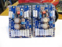
Isnt there supposed to be 2:1 ratio of feedback power resistors to fet source resistors.
Source resistors are 2x .47 ohms
Feedback resistors are 1x .47
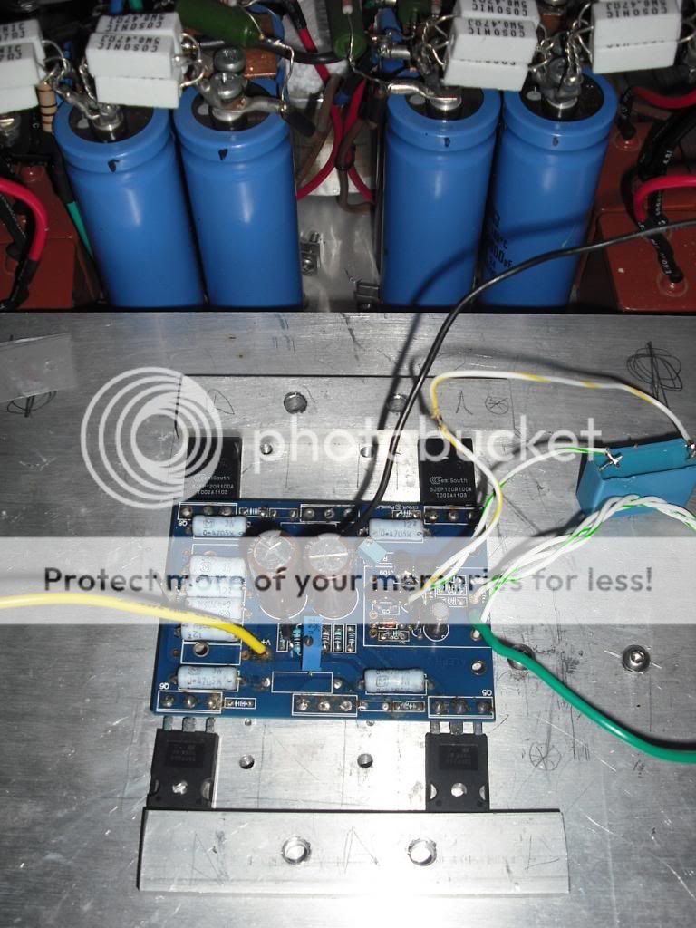
Sorry the picture isn't the most clear
Best
Update
Thank you for reply
Some measurement:
PSU +-22V
Time of power up 30min
Offset 0V at 30min, cold I think about 15mV
R8= 8,9V (fixed 830ohm)
across 500ohm pot 1,8V
Voltage across 0,47 3W resistors about 500mV (+- 10mV)
The numbers look good?
More in a few hours!!!
Alberto.
Thank you for reply
Some measurement:
PSU +-22V
Time of power up 30min
Offset 0V at 30min, cold I think about 15mV
R8= 8,9V (fixed 830ohm)
across 500ohm pot 1,8V
Voltage across 0,47 3W resistors about 500mV (+- 10mV)
The numbers look good?
More in a few hours!!!
Alberto.
Thank you for reply
Some measurement:
PSU +-22V
Time of power up 30min
Offset 0V at 30min, cold I think about 15mV
R8= 8,9V (fixed 830ohm)
across 500ohm pot 1,8V
Voltage across 0,47 3W resistors about 500mV (+- 10mV)
The numbers look good?
More in a few hours!!!
Alberto.
Looking real good. Let us know how it sounds. Seems you have motivated me to figure mine out.
Not for me. I am going to try again and if it doesnt work, I am using to light cooking fire.everything is just little math and going in FAB mode
after that - Mad Scientist mode , for Aleph CCS AC gain (THD spectra) setting

Not for me. I am going to try again and if it doesnt work, I am using to light cooking fire.
do not worry - I made tons of gray smoke more than you ; even if you try , you'll need 3 lives to be even near that
......... it's much easier to be clever (fart) post hoc ; being clever and make a hoc is where men are different from boyz
your truly , Mighty Boy ZM

Offset problem!
I have offset problems: (
Yesterday In my desk the variation was only 30mV, but in the chassis is too high!.
Some measurement with input shorted and resistor load:
0min 300mv cold
3min 30
5min 5
15min -65
20min -80
30min -100
40min -138
45min -142 stable
Both channel with similar problem..
Any Idea?
Sorry if is a silly question but this is my first Solid State project..
Alberto:
PS: the amp sound very good
Did you try to trim the offset after it heated up?
What are your case temperatures. The change is most likely due to thermal drift casuing change in bias point as the fets and sinks get hot.
I was thinking about this project the other night, contemplating what might be wrong with mine, and a thought actually appeared. I know, shocking. i am not syaing it a good one, but here it goes. I think the Jango is a bad idea. While you can get the offset and Dc conditions set and stable, the AC conditions are going to be non ideal. If the SS was loaded with a simple CCS, like the F2, i would expect an improvement in performance equal to the improvement of the SS fet vs standard mosfet. With the ACS, we have something completely different. You have an active current source that is basically trying to track/follow the output of the lower fet and contribute equally, or as close as determined by ACS setting, as possible. If you had two identical fets, like in the original, I would expect excellent results, as both fets are matched and respond to the same signal in similar ways. With the Jango, you have very different fets, with different operational parameters when fed the same AC signal. While I am sure the top fet can do the job and the amp can sound nice, it seems limited from the beginning, simply because the fets will respond differently due to fact that they are different. I can see cohesive effort with similar fets, but a sort of battle, with dissimilar fets.
Dunno. Maybe just an excuse to give up. Gonna try till something burns.
- Status
- This old topic is closed. If you want to reopen this topic, contact a moderator using the "Report Post" button.
- Home
- Amplifiers
- Pass Labs
- The Aleph Jango