no change of 390R resistor and keeping mosfet
if you don't understand schematic enough to know why values are as they are, then try to listen to advices
I already told you everything you need to know
- redo second channel with quieter version of CCS for input LTP
-decrease gain slightly if that suits you
after that, all you can (and it is best ) - replace existing pcbs, keep output mosfets and choose Aleph J (Aleph 30 with JFet input)
no hum, no noise, better sound
Here are the best Aleph j boards you can find on earth:
https://diyaudiostore.com/collections/power-amplifier/products/aleph-j?variant=5941228356
But currently sold out.
https://diyaudiostore.com/collections/power-amplifier/products/aleph-j?variant=5941228356
But currently sold out.
Very thanks! I will be waiting for them. But want to try last two thinks.
-reduce gain
-change irf9610 dor jfets.
If this dont give me what i need i wil stop this war hehe
Please tell me. I need to match 2sj109 to 10mA? And can i keep ccs even when i use jfets? I think yes
-reduce gain
-change irf9610 dor jfets.
If this dont give me what i need i wil stop this war hehe
Please tell me. I need to match 2sj109 to 10mA? And can i keep ccs even when i use jfets? I think yes
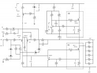
Yes i know but this is not my pass, im trying to help my good friend. I have measured elements and shematic is near same like i posted. It have couple changes. Take a look. LIke i said gain is to much. 22.1k is changed for 47k, 10k gain resistor is 220k. 1k with 220uf is 4,2k with 10uf capacitor . I know this is place where i can chagne cut off. and he have swith that chose 0.22uf or 10uf capacitor. 0.22uf with 4.2k resistor is 100hz cut of i think, he have subwoofer for stereo so he have 100hz cutoff .

Situation look that. At first when i putt 1khz 1vpp(25% laptop volume) on pass i get 41vpp so gain was to much it was x40. I change 47k on 20k, 220k to 10k. For now from 1vpp i get 3vpp, so gain is x3. From laptop i have max 4,4vpp and it give me over 14vpp not max from pass but for now i have absolute no noise, even with head putted to 97db speaker.
well, I'm giving you some slack because of fact that English is not your primary language..... but - I did ask for exact values in actual amps
you're slightly leading me around in circles
in case that you posted actual values, problem could be solved after two posts, not after 2-3 pages
it is not wonder that you have excessive hiss if you had those values for NFB
220KK/4K2 is pushing gain too high, ratio being 52x, instead original 10x !!!!!!!
replace 220K with 100K
replace 4K2 with 10K
write back what results are
do that first, observe results and only then ask more questions
I know that my english is poor,sorry.i have done some measurments. I have change 10k for 20k. 4.2k with 10uf /0.22uf must be. Becouse with 0.22uf capacitor i have 100hz cut off. I have start 1khz and set volume to have 10vpp from pass ouput. And go down to 30hz, still have 10vpp, on 25hz i have 9vpp so 10uf capacitor with 4,2 resitor give my full frequency.
I dont calculate this, some one have done this years ago. But he calculate that F3 100hz will be with 4.2k and 220nf, and full range will me 4.2k and 10uf. The gain resistor (orginal 10k) change my cutoff? .My friend haved 86db fronts with subwoofer and pass was cutoof on 100hz with 4.2k 0.220uf and 220k gain resistor. He change fronts for 100db , he will have sub again. And it was problem with to much gain and very big noise. So i have change gain, no noise for now, but 100hz cutoff he still needs.

ZM has shown far more patience in this project than can be expected from any mortal human.
Those Chinese clone boards were illegitimate from the first day they were sold; and they were assembled without any regard to proper electronic construction technique. It is impossible to tell whether the dodgy PCBs or the indifferent construction is the problem. Probably a combination of both.
The best advice that was given was to start over with new, proper, Aleph J boards.
Last edited:
I think he's saying that it's working now with the excessive gain fixed and values selected so that they only care about performance above 100Hz because there is a separate powered sub and there is no noise or hiss from 97dB speakers even with his ear right next to it.
Everyone calm down and listen to some Yanni
Cheers
Stephen
Everyone calm down and listen to some Yanni
Cheers
Stephen
")
Referencing the attached schematic, in all of the Aleph schematics I have seen, the resistor in the R18 position has always had a value of 1k5. However, it seems there are some A 30s that were fitted with 4k75 in that position. Is there a compelling reason to favor a value of 1k5 over 4k75 in that position? (Of course, you would also need to change R19 value to maintain reasonable bias).
Attachments
- Home
- Amplifiers
- Pass Labs
- The Aleph Design Reloaded