The 300B SE amp I mentioned above is this one.
NEM A300SE Röhrenvollverstärker
The only thing, I ordered it for 4 Ohms speakers, therefor its output impedance close to 0,6 Ohms, and bass is quite impressive. Nobody believes that they listen 300B SE with such a bass.
NEM A300SE Röhrenvollverstärker
The only thing, I ordered it for 4 Ohms speakers, therefor its output impedance close to 0,6 Ohms, and bass is quite impressive. Nobody believes that they listen 300B SE with such a bass.
Several months ago I have got new speakers - PMC EB1i, also I have three amps -
1) tube 300B SE from Eraudio (60kg weight, Zout=0,6 Ohms)
2) Zen9 with LD1010 - 3x2SK1058 - 3x2SK1058 3,8A Zout=0,8 Ohms
3) Zen9 monoblocks with LD1010 - 3x2SK1529 - 3x2SK1529 4,8A Zout=0,4 Ohms
and a preamp with 22dB amplification based on SIT transistors KP926A.
The amp 1) acts as a reference for the mids and highs reproduction.
The speakers do not have impedance deeps, impedance is very flat from 50Hz till 500Hz in the region 3,8...4,2 Ohms.
I have tested very simple way of achieving good bass reproduction. In Zen9, just changed resistors of NFB divider to 3k4 and 6k8, also adjusted NFB compensation cap to 30...60pF. Zout now are 0,34 and 0,15 Ohms, it is comparable with speaker cables resistance. Power supplies are external, 2x1kW trafos.
Bass now almost perfect. Very tight and powerful in 6x5,5x3m room. As for highs, they are the same, or very little worse, almost impossible to distinguish.
Thanks for the update. It's so great to image a ZV9/F3 with powerful bass..
Hope someday I have time to build it.
For the Power Zen9 being discussed here a choice of preamp becomes quite important, since it must work for 3k4 impedance and provide large amplification.
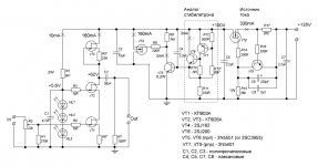
As a possibility, I use the following preamp. Analogs for transistors are:
KP903 <- CP650
KP926 <- 2SK60
The preamp itself is three first transistors only. The rest of schematics is shunt power supply.
As a possibility, I use the following preamp. Analogs for transistors are:
KP903 <- CP650
KP926 <- 2SK60
The preamp itself is three first transistors only. The rest of schematics is shunt power supply.
Attachments
Last edited:
I own a FW F3 now and doesn't know that... sounds very important for the impedance matching... but doesn't quite understand what you wrote. Could you give more details? Thanks,For the Power Zen9 being discussed here a choice of preamp becomes quite important, since it must work for 3k4 impedance and provide large amplification.
.
I own a FW F3 now and doesn't know that... sounds very important for the impedance matching... but doesn't quite understand what you wrote. Could you give more details? Thanks,
I do not advise to touch Nelson's masterpiece, but if one would occur a "vandal" and decided to experiment with it, I could propose to substitute: R1 by 3k4, R2 by 6k8, C9 would not change (original schematics seems to be overcompensated).
After doing this, one can get a problem with preamp, since now we have Ku=2 and input F3 impedance close to 3k4.
For this occasion, preamp schematics as I indicated above could be quite fitting to the situation.
Vladimir, Haven't you lower the gain to 2? But, incresed the feedback? with R1 3k4 and R2 6k8
Yes, obviously, this way we increase the feedback and proportionally decrease the output impedance of F3. This leads to more tight bass, and does not cause trouble with highs since feedback is local (short path). At this, value and quality of C9 is quite important for subjective sound perception, I like silver-mica, and even slitely undercompensated square wave reproduction.
There is one more reason for decreasing the R1 - it is high gate capacitance of LU1014, even if it is cascoded. Charging it through 10K resistor is not the same as charging some few pF of tube's grid or a gate of small j-fet. Were is no obvious compromise, but unloading F3 from some problems and moving them to preamp seems justified.
Yes,
I understand. It sounded a little unorthodox but I see. I wasn't even sure about the RefDes (R1 -R2) I don't have those numbers on my schematic but I think I new what you were talking about. Very interesting work Vladimir.
After my current F5 project I will get back to an F3/ZV9 or? for the top end. I have a stash of SemiSouth devices also.
So many ideas so little time...
Last edited:
F3/ZV9 topology finally caused me to go with extraordinary power consuming preamp, which is not only high-voltage and high-current, but also no NFB. To my observation, there must be at least one No NFB component in the system along signal path, in order to stop speaker back EMF propagation from output to input through NFB resistors. This is not an easy way, but final sound justifies it. Speaking about sound, for instance Track 4 "Flesh and Blood" from "Bowers&Wilkins Demo Disk Very Audiophile New Recordings" 2006, voice reproduction with ZEN9 is even more "fatty" articulated and better to my opinion than with 300B SE amplifier.
What about modifying Aleph CS gain? Are these changes different than global gain changes regarding sound?
Elemination of the current source modulation would decrease greatly deviations of current consumption from the power rail, what makes better highs and worse bass. But it seems unrealistic to go fo 10A idle current, therefore I uses Nelson's invention together with giant polypropylene 100uF cap at the power rail.
By decreasing R1 and R2 we almost do not make problems to highs, and make easier bass in addition to the Aleph CS.
Anyway, I plan next project based on the Power Follower 99, with 5-6A idle current and MOSFETs from Fairchild.
Well, I tried to remove comletely the components of current source modulation from 4,8A Zen9 monoblocks. So, now it is without Aleph CS. With a resistive load 5,1 Ohms, I have measured 17,8V RMS non-distorted sine signal, it is 60W RMS output power.
As for listening impressions, as was expected, now it is more transparent, better microdynamics, hardly possible to distinquish from SE 300B tube amp. Bass has become a bit less impressive, but I guess it will remain without Aleph CS. At the moment I do not have any wishes as per further improvements.
As for listening impressions, as was expected, now it is more transparent, better microdynamics, hardly possible to distinquish from SE 300B tube amp. Bass has become a bit less impressive, but I guess it will remain without Aleph CS. At the moment I do not have any wishes as per further improvements.
Elemination of the current source modulation would decrease greatly deviations of current consumption from the power rail........... I uses Nelson's invention together with giant polypropylene 100uF cap at the power rail.
................ I tried to remove comletely the components of current source modulation from 4,8A Zen9 monoblocks....I have replaces small 0,15uF shunts by bigger ones (5u6 and 6u8).
Hi,
Allow me to I summarise:
1) Removal of CCS
2) Adding of 100uF film cap to the power rail
3) Bypass the power caps with bigger film cap
Am I correct?
Have you gone thru this thread: http://www.diyaudio.com/forums/power-supplies/126697-bypassing-psu-capacitors-effective.html ?
Hi,
Allow me to I summarise:
1) Removal of CCS
2) Adding of 100uF film cap to the power rail
3) Bypass the power caps with bigger film cap
Am I correct?
Have you gone thru this thread: http://www.diyaudio.com/forums/power-supplies/126697-bypassing-psu-capacitors-effective.html ?
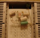
Not correct, the big polypropylene caps already were at PS rail and output cap, but inside the schematics I used small 0,15uF shunts. Now they are 5u6, you can seen them on the foto (view from the bottom).
As for bypassing PS filter caps, this may have effect if you want to filter additionally the HF noise coming from non-perfect diode bridge. This kind of noise could be hardly detectable by standard instruments. Doing this, one must also control possible parasitic ringing, which's possibility depends on wiring and other design features.
Last edited:
A revised ZV9 (F3)
Thanks VladimirK for your 50W inspiration. Although I didn't need more watts for my 101dB speaker, I still tried to learn from your 50W version. Increase bias current, bypass Alpha CS, Modulated Cascode Cap and change NFB resistor value...
Here is the list and result from the final mod: (sorry, I still touched the master's work)
(1) Reduce R8 and R4 to 1R. Increase bias current around 1.9A.
(I test several resistor values many times, this set works best in the balance of THD and high order harmonics. I prefer lowest high order harmonics than lowest THD)
(2) Increase the Cap value in Cap multiplier to 2200uf
(3) Tweak PS part cap a little, add one set 47000uF CRC filter.
(4) Increase C2 to 470uF ELNA RSK and by pass by 2uF Rel Cap TFT.
(5) Increase C7, C3 to 470uF too, also bypass it (this time Nichicon BPS)
(6) One final key step is... use Distortion Analyzer to fine tune the P1 and P2 value... it change the whole spectrum of distortion in quantity and distribution.
Modulated Cascode (P1) can change the THD and HD distribution around 1W outout. Alpha CS (P2) can change the THD and HD distribution from 6W above.
And the result:
1. I got 40uV noise when input short (better than original 100uV)
2. THD @ 1K,1W 0.002% (original 0.01%) with almost ZERO 5th or above harmonic distortion.
3. THD @ 20K,1W lower to amazing 0.05% (original is 0.19%)
4. THD @ 1K, 10W 0.015% (original is 0.1% with more High order harmonics)
Without too much time to crazy about this numeric results. I already start the listening.
Wow... it never shounds that fantastic! Bass is more solid, high is more clean but still sweet. Music density is double and 3D image is clearer...
So I write this feedback to thanks you and let you know, NP's ZV9 circuit
is really a good platform to tweak out the best sound you want...
Also I have replaces small 0,15uF shunts by bigger ones (5u6 and 6u8). The monoblockes are made by p-to-p soldering, on the 2mm teflon plate. Inp and Outp connectors are gold plated bronze.
Thanks VladimirK for your 50W inspiration. Although I didn't need more watts for my 101dB speaker, I still tried to learn from your 50W version. Increase bias current, bypass Alpha CS, Modulated Cascode Cap and change NFB resistor value...
Here is the list and result from the final mod: (sorry, I still touched the master's work)
(1) Reduce R8 and R4 to 1R. Increase bias current around 1.9A.
(I test several resistor values many times, this set works best in the balance of THD and high order harmonics. I prefer lowest high order harmonics than lowest THD)
(2) Increase the Cap value in Cap multiplier to 2200uf
(3) Tweak PS part cap a little, add one set 47000uF CRC filter.
(4) Increase C2 to 470uF ELNA RSK and by pass by 2uF Rel Cap TFT.
(5) Increase C7, C3 to 470uF too, also bypass it (this time Nichicon BPS)
(6) One final key step is... use Distortion Analyzer to fine tune the P1 and P2 value... it change the whole spectrum of distortion in quantity and distribution.
Modulated Cascode (P1) can change the THD and HD distribution around 1W outout. Alpha CS (P2) can change the THD and HD distribution from 6W above.
And the result:
1. I got 40uV noise when input short (better than original 100uV)
2. THD @ 1K,1W 0.002% (original 0.01%) with almost ZERO 5th or above harmonic distortion.
3. THD @ 20K,1W lower to amazing 0.05% (original is 0.19%)
4. THD @ 1K, 10W 0.015% (original is 0.1% with more High order harmonics)
Without too much time to crazy about this numeric results. I already start the listening.
Wow... it never shounds that fantastic! Bass is more solid, high is more clean but still sweet. Music density is double and 3D image is clearer...
So I write this feedback to thanks you and let you know, NP's ZV9 circuit
is really a good platform to tweak out the best sound you want...
Last edited:
- Status
- This old topic is closed. If you want to reopen this topic, contact a moderator using the "Report Post" button.
- Home
- Amplifiers
- Pass Labs
- The 50W version of Zen9